AutomationControlElectrical DesignElectrical WiringHow ToMotors
How to Control a Single-Phase Motor from Multiple Locations?
Controlling the ON-OFF Operation of a 1-Phase Motor from Multiple Places using Contactor and Pushbuttons
In large industrial and commercial premises, there are scenarios where we need to control a three-phase or single-phase motor from different locations. Similarly, we may need to control a water pump motor from different places in domestic and home applications. In the following wiring tutorial, we will discuss how to control the starting and stopping operations of a single-phase motor from different locations using a contactor and push-button switches, with the help of power and control circuit diagrams.
Related Posts:
- Auto & Manual Control of 1-Phase Water Pump Motor using Float Switch
- Auto & Manual Control of 3-Phase Water Pump Motor using Float Switch
Components Needed
- Single-Phase Motor
- Contactor
- Thermal overload Relay)
- 1-P & 2P-MCB
- 3 Nos. of NO/NC Pushbuttons
- Single Phase Supply
- Wires & Cables
Control Wiring Diagram
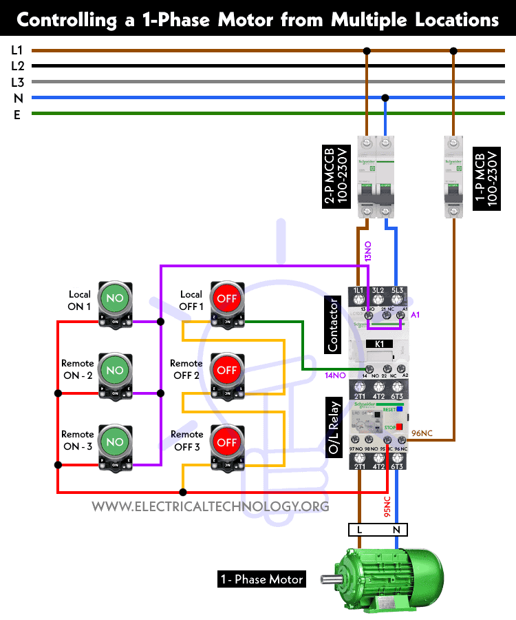
Wiring the Control Circuit
Power Circuit:
- Wire and connect the L1 and L3 terminals of the contactor to the 2-pole MCB via Phase and Line wires.
- Connect a 2-pole MCB to the single-phase 120V to 230V power supply, mainly from the 120V-240V panel, 230V consumer unit or distribution board.
- Wire and connect the L1 and L3 terminals of the contactor to the output of the 2-pole MCB via Phase and Line wires. Keep in mind that the O/L relay is already connected to the contactor.
- Connect the T1 and T3 terminals of the overload relay to the “L” and “N” terminals of the single-phase motor.
- Connect the earth/ground wire to the motor terminal for proper protection.
Related Posts:
- How to Start & Stop a 3-Phase Motor from Multiple Locations?
- How to Control a 3-Phase Motor from Multiple Places?
Control Circuit:
- Connect a wire to the first terminal of each start pushbutton (local and remote). Now, connect this wire to the 13-NO terminal of the contactor. Add a jumper wire between the 13-NO and A1 terminals of the contactor.
- Connect a wire to the second terminal of each start pushbutton (local and remote). Now, connect this wire to the 95-NC terminal of the thermal overload relay.
- Connect all three local and remote stop pushbuttons in series to the 95-NC terminal of the thermal O/L. Then, connect a wire from the last stop pushbutton to the 14-NO terminal of the contactor.
Working of the Circuit
- When the operator presses the local start pushbutton, the contacts close, leading to the energization of the contactor. Thus, the motor starts to run.
- When the operator presses the local stop pushbutton, the contacts open, returning to their initial state. This way, the contactor de-energizes, and the motor stops.
- The same process applies to all the additional remote pushbuttons installed in different locations to control the motor from various places.
- Due to the interlocking mechanism, only one operation (either stopping or starting) can be performed at a time. This prevents damage to the circuit and avoids overheating/burning the connected motor.
Related Posts:
- ON / OFF Control of a 3-Phase Motor Using a DOL Starter
- ON / OFF 3- Phase Motor Using 8-PIN Relay and DOL Starter
- ON / OFF 3- Phase Motor Using 14-PIN Relay and DOL Starter
- ON / OFF 3- Phase Motor Using 11-PIN Relay and DOL Starter
- Compressor Motor Control in Refrigeration Using Soft Starter
- Three Phase Slip Ring Motor Wound Rotor Starter
- Two-Speed, One-Direction, 3-Phase Motor Power & Control Diagrams
- Two-Speed, Two-Directions, 3-Phase Motor Power & Control Diagrams
- Dahlander Motor: Speed Control using Dahlander Connection
- Even More Power & Control Wiring Diagrams


