Difference Between CTL and Non-CTL Breakers & Load Centers
Identification of CTL and Non-CTL Panels and Circuit Breakers
CTL Panels & Breakers
CTL stands for Circuit Total Limitation. It is a safety feature used in modern load centers, electrical panels, and circuit breakers. This feature has been required since 1965 by NEC to limit the total number of circuits that can be installed in a panel to prevent panel overcrowding and overheating.
A CTL panel is designed with mechanical rejection features that prevent installing more circuit breakers than the panel is rated for or designed to handle.
It contains rejection tabs or notches on the bus stab or breaker slots and allows only approved tandem (duplex) breakers in designated spaces. This feature was Introduced after the circuit limit rule in the NEC.
In simple terms, a CTL version of panel with special design prevents installing extra breakers beyond the panel’s listed circuit capacity. Thus, CTL breakers only fit in CTL-listed panelboards or load centers. Also, the panel itself prevents installing extra tandem/duplex breakers in non-approved slots. Hence, it ensures the maximum number of circuits specified by the manufacturer is not exceeded.
The purpose of CTL load center is to stop electricians from overcrowding the panel with additional circuits that could overload the busbars.
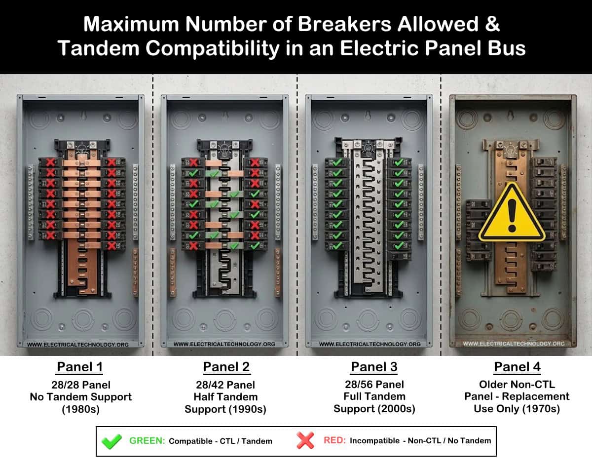
For example, a CTL electric panel might be labeled “20/30” which means 20 breaker spaces / 30 circuits. In this case, only certain spaces allow tandem breakers to reach a maximum of 30 circuits. If you try installing tandem breakers in non-approved slots, the rejection tab prevents it.
How to Identify a CTL Panels & Breakers
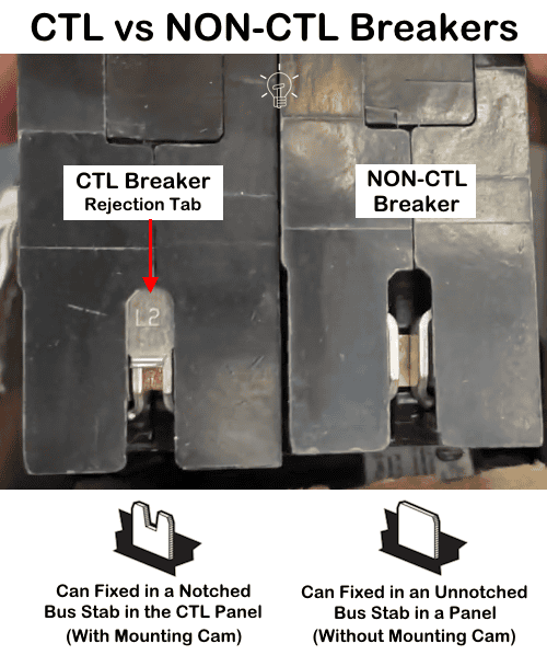
If there is a breaker rejection notch, tab, plastic foot on bus connection side, it is a CTL load center. This tab or notch prevents installation in non-approved slots of the panel. Moreover, in CTL load centers, panel label printed on it shows circuit limits and markings such as “CTL Type, CTL Class, CTL” or circuit capacity.
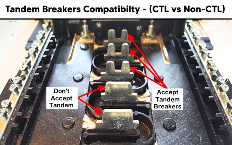
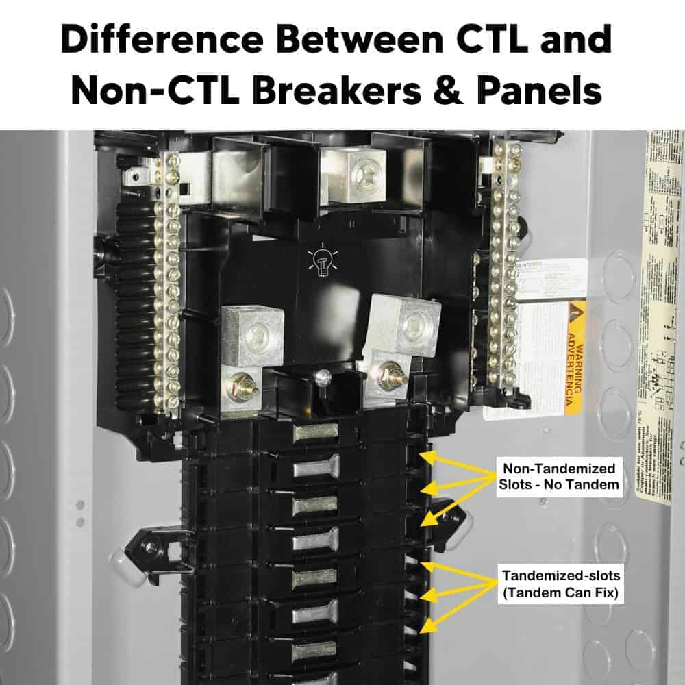
Similarly, look inside the panel at the breaker slot where the breaker attaches to the bus stab. In CTL panels, some slots have rejection grooves or physical barriers. It means, tandem breakers only fit in specific spaces.
In addition, It can be identify by look at the panelboard nameplate label.
For example, if it says “20 Spaces / 30 Circuits”, it means 20 breaker slots. Only certain slots allow tandem breakers for maximum 30 circuits. If the panel enforces this limit physically, it is a CTL panel.
Non-CTL Breakers & Panels
A Non-CTL panel does not have circuit-limiting rejection features i.e. breaker slots do not restrict installing tandem breakers. In other words, more breakers can physically fit than the panel was originally designed for.
It means, all breakers can snap over the hot busbar and if overcrowded (use of more breakers than the designated numbers), it may cause overloading, overheating and hazardous fire.
Non-CTL was common in older panels manufactured before 1965–1968. Without CTL restrictions, people often installed too many circuits, leading to overloaded busbars, excessive heat and fire hazards.
How to Identify a Non-CTL Breakers & Panels
If there is no rejection tab (notch) beside the busbar(s), it is a Non-CTL panel and the breaker can snap into almost any slot.
Similarly, If the breaker looks completely flat on the back, it is usually Non-CTL breaker. In addition, slots are uniform with no rejection feature and tandem breakers can fit in any position.
In addition, panels manufactured before 1965–1968 were generally Non-CTL because the circuit limiting rule was introduced later in the National Electrical Code.
Why Non-CTL Breakers Still Exist
Although new panels are CTL-type, Non-CTL breakers are still manufactured for replacement purposes in older panels that originally did not have CTL rejection features.
However, using a Non-CTL breaker in a CTL panel violates the listing requirements of the panel and is generally considered a violation of NEC installation rules (such as equipment being installed according to listing and labeling as per NEC 110.3(B)).
Precautions:
- Always disconnect the power supply by switching OFF the circuit breaker at the main service panel before performing any electrical work.
- Electrical equipment must be installed according to manufacturer instructions as required by the NFPA and NEC 110.3(B)).
- Never touch the terminal screws above the main breaker. These terminals are always energized and remain live even when the main breaker is switched OFF.
- If you are unsure about any part of the installation, consult a licensed electrician and ensure compliance with applicable local electrical codes.
Disclaimer: Electrical work is dangerous. The author assumes no responsibility for any loss, injury, or damage resulting from the use or misuse of this information, including improper circuit installation.
Resources:
Related Posts:
- National Electrical Code (NEC) Requirements for Panelboards
- Busbar, Bus Stab, Breaker Slot and Circuit Space in a Panel
- What is a Backfeed Main Breaker in an Electric Panel?
- What is the Max Number of Breakers Allowed in a Main Panel?
- What is Double Tapped Breaker and Double Lug in Main Panel
- What Happens if the Neutral is Lost in the Main or Subpanel?
- Why Must Neutral and Ground Wires Be Bonded in the Main Panel?
- Why are Neutral and Ground Wires Separated in a Subpanel?
- Should GFCI Protection Be in the Main Panel or Receptacle?
- Difference Between BR and CH Breakers and Load Centers
- Difference Between Homeline and QO Breakers and Panels
- Difference Between 1-Pole and 2-Pole Breakers – NEC & IEC
- Can the Neutral Wire Cause Electric Shock? Different Cases
- Will I Get an Electric Shock If I Touch the Ground Wire?
- Will a Man Get an Electric Shock If He Hangs on a Live Wire?
- What Happens When You Touch an Electrical Busbar?
- Can We Use AC Circuit Breaker for DC Circuit & Vice Versa?
- Can I Use a 240V Breaker on a 120V Circuit and Vice Versa?
- Can You Use 15A Breaker on 20A Circuit and Vice Versa?
- What is the White Powder on the Circuit Breaker Terminals?
- Why Doesn’t a Standard Breaker Protract Against Ground Faults?
Sizing & Rating
- How to Size a Load Center, Panelboards and Distribution Board?
- How to Determine the Right Size Capacity of a Subpanel?
- How to Size a Circuit Breaker? Breaker Size Calculator
- How to Determine the Number of Circuit Breakers in a Panel Board?
- How to Find the Right Wire Size for 100A Service 120V/240V Panel?
- What is the Correct Wire Size for 100A Breaker and Load?
- How to Find the Number of Lights on a Single Circuit Breaker?
- How to Size a Breaker and Wires in AWG with EGC for Load?
- How to Size a Breaker and Wires in AWG with EGC for Load?
- How to Size a Branch Circuit Conductors with Protection?
- How to Size Feeder Conductors with Overcurrent Protection
- How to Size Service-Entrance Conductors and Feeder Cables?
- How to Size Equipment Grounding Conductor (EGC)?
- How to Size Grounding Electrode Conductor (GEC)?
- How to Find the Proper Size of Wire & Cable In Metric & Imperial Systems
Wiring Tutorials
- How to Wire 120V & 240V Main Panel? Breaker Box Installation
- How to Wire a Subpanel? Main Lug Installation for 120V/240V
- How to Wire 120V & 208V – 1 & 3-Phase Main Panel? 3-Φ Load Center Wiring
- How to Wire a GFCI Circuit Breaker? 1, 2, 3 4 Poles GFCIs Wiring
- How to wire a GFCI Outlet? GFCI Wiring Circuit Diagrams
- How to Wire an AFCI Combo Switch – AFCI Switch Wiring Diagrams
- How to Wire a Single-Pole Circuit Breaker in a 120/240V Panel
- How to Wire a Two-Pole Circuit Breaker in a 120/240V Panel


Great article! I really appreciate the detailed insights shared here.