Wiring Installation of a Home/Away Smart Wireless Switch for Lighting Control
In todays smart devices installation series, we will discuss the adorne® Home/Away Wireless smart switch with Netatmo by Legrand. The installation guide, along with wiring diagrams, shows how easily the wireless switch can be installed in minutes to control lighting from multiple locations, even without the need for additional wiring or a gateway system.
What is Home/Away Wireless Smart Switch
The Legrand Home/Away wireless smart switch with Netatmo (WNAL33W1), is a battery-powered control device designed for smart lighting systems. It allows users to activate preset “Home” and “Away” lighting scenes with a single press. These scenes automatically adjust multiple lights at once for convenience and safety.
This 1-gang smart switch works wirelessly with primary smart switches and does not require physical wiring. It can be installed in a box or mounted anywhere on the wall, such as near the main entrance or garage door. When leaving home, it can turn off selected lights, and when arriving, it can switch them on instantly.
The device operates as part of a smart ecosystem using a gateway and mobile app. Users can create and manage lighting scenes, connect multiple smart devices, and control everything remotely. It improves flexibility, energy efficiency, and overall home automation experience.
Good to Know:
- Smart wireless switches do not directly control a load. It requires primary smart devices used with load e.g. lighting points to control from different locations in 3-way or multi-way switching control.
- This smart wireless device is powered by a replaceable long-life 3V lithium battery cell (CR2032).
- The installation process of WNAL33W1 is same for other smart wireless home/away switches by Legrand such as WNAL33M1 or WNRL33WH, wake/sleep switches such as WNAL43W1, WNRL43NI, WNRL43WH, or WNRL43LA, and wireless smart switches such as WNRL23WH.
- These wireless smart switches by Legrand is compatible with Amazon Alexa, Apple Home Kit, Google Home and other home automation systems.
- The smart wireless switch can be used to create and manage 8 scenes per system using the Home+ Control app in commercial, multi-dwelling units, and residential applications.
- A Smart Gateway is required for the Legrand wireless smart switch in conjunction with other wired smart devices i.e. smart switches and dimmers. For proper operation, it must also be paired with an adorne® or radiant® smart switch with Netatmo, or a smart plug-in switch with Netatmo.
Wiring a Home/Away Wireless Smart Switch
The Home/Away Wireless Smart Switch is a battery-powered scene controller. It does not require line/load wiring, unlike traditional switches. Instead, it communicates wirelessly with other Netatmo smart devices.
However, this switch requires grounding wire when mounted in an electrical box or replacing with an existing switch. The installation is fast, flexible, and ideal for multi-location lighting control without running new cables. This way, the connected load can be controlled through the mobile app or manual operation.
Although no physical wiring connections are required during installation, it is recommended to turn off power at the breaker or main service panel as a safety precaution (especially when mounting the device in an electrical box).
You can install the smart warless switch in two ways:
- Inside a standard electrical wall box
- Directly on a wall surface (no box required)
Installation in Electrical Box
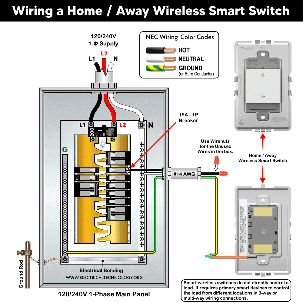
Remove the label at the back of the device. This exposes the bult-in green grounding wire in the switch.
Locate the ground wire (from branch circuit) in the box (mostly, bare conductor, green or green with yellow stripe). Connect the device ground wire to the box ground using the provided wire connector. This is the only conductor required to install.
As the device is wireless, no line, neutral, or load connections are needed to connect. If installed alongside wired smart devices (e.g., WNAL10, sofTap switch or other wired Netatmo device ), terminate spare wires as per their instructions.
In case of replacing with an existing switch, handle other wires carefuly (if present) i.e. add wire connectors to the bare conductors and safely keep inside the box.
If you are going to install in Multi-Gang, replace single frame with multi-gang frame. Snap device into the frame and secure with mounting screws. Finally, fix the switch to the wall box using screws.
Click image or open in a new tab to enlarge
Mounting on the Wall Surface
If not using a box, select a proper location where you need to mount the switch.
Apply double-sided adhesive strips at marked positions. Stick onto a smooth surface (tiles, finished wall).
Adhesive is not recommended for heavy or premium wall plates. In this case, use drywall screws or anchors for rough surfaces.
After installation, attach the wall plate by snapping it onto the frame and adjust fit using built-in click positions.
Power and Setup
Remove the battery insulation tab (CR2032 battery include). To pair with system, install the Legrand Home + Control app and follow app instructions to connect to home network or pair with gateway and smart devices.
For smart lighting control, follow this step-by-step guide for the Netatmo system to select your gateway, primary device, and add-on devices.
To enable Amazon Alexa, Google Home Voice Control Integration or or voice assistance to create scene for adorne & radiant® With Netatmo, follow this setup guide for automation.
To verify the operation, the LED indicator will blink green when connecting and turn solid when connected successfully.
If you need to reset to the factory default (when Required), press and hold the EZ button for 7 seconds. LED will blink red, then turns off. The device reset is complete.
Instructions & Precautions
- Make sure to disconnect the power supply by switching OFF the breaker in the main panel before doing any electrical work.
- The wire length from smart switch to other companion device should not exceed 300 ft (90 meters).
- Smart devices are only suitable for indoor use, and should not be used for medical applications.
Disclaimer:
- The author will not be liable for any losses, injuries, or damages from the display or use of this information or if you try any circuit in wrong format. So please! Be careful because it’s all about electricity and electricity is too dangerous. If you are unsure, contact a licensed electrician to do it according to the local area codes.
Resources:
Smart Devices Wiring Series
- How to Wire a Smart Switch in a 120/240V Load Center
- How to Wire 120/240V Smart Load Center with Smart Breakers
- How to Wire a Smart Breaker in a Smart 120/240V Panel
- How to Wire a Smart GFCI Breaker in a 120/240V Smart Panel
- How to Wire Smart AFCI/GFCI Breaker in a Smart Load Center
- How to Wire a 15A Wi-Fi Smart Outlet in a Smart Panel
- How to Wire 15A and 20A Wi-Fi Smart GFCI Outlets
- How to Wire Z-Wave Smart Switch, Dimmer & Fan Speed Controller
- How to Wire a Digital and Wi-Fi Smart LED Dimmer Switch
- How to Wire a Smart Switch Companion with a Smart Switch
- Wiring a Smart Dimmer Switch Companion with a Digital Dimmer
- How to Install a Wire-Free Smart Dimmer Anywhere Companion
Wiring Standard GFCI & Breakers
- How to Wire a 1-Pole Breaker
- How to Wire a 2-Pole Breaker
- How to Wire a 3-Pole Breaker
- How to Wire a 1-Pole GFCI
- How to Wire a 2-Pole GFCI
- How to Wire a 3-Phase, 3-Pole GFCI
- How to Wire a Tandem Breaker
- How to Wire GFCI Circuit Breakers
- How to Wire an AFCI Breaker
Wiring General Outlets & GFCI/AFCI Receptacles
- How to Wire an Outlet Receptacle? Socket Outlet Wiring Diagrams
- How to wire a GFCI Outlet?
- How to Wire an AFCI Outlet?
- How to a Wire 3-Way Combination Switch and Grounded Outlet?
- How to Wire a 15A – 125V Outlet – NEMA 5-15 Receptacle
- How to Wire a 20A – 125V Outlet – NEMA 5-20 Receptacle
- How to Wire a 15A – 250V Outlet – NEMA 6-15 Receptacle
- How to Wire a 20A – 250V Outlet – NEMA 6-20 Receptacle
- How to Wire a 50A – 125/250V Outlet – NEMA 14-50 Receptacle
Switches Wiring
- How to Wire Single Pole, Single Throw (SPST) as 2-Way Switch?
- How to Wire Single Pole, Double Throw (SPDT) as 3-Way Switch?
- How to Wire Double Pole, Single Throw Switch? Wiring DPST
- How to Wire Double Pole, Double Throw Switch? Wiring DPDT
- How to Wire Double Switch? 2-Gang, 1-Way Switch – IEC & NEC
- How to Wire 4-Way Switch (NEC) or Intermediate Switch as 3-Way (IEC)?
- How to Wire Auto & Manual Changeover & Transfer Switch – (1 & 3 Phase)
Sizing Breakers, Wires & Panels
- How to Size a Load Center, Panelboards and Distribution Board?
- How to Determine the Right Size Capacity of a Subpanel?
- How to Find the Right Wire Size for 100A Service 120V/240V Panel?
- How to Size a Circuit Breaker?
- How to Find the Proper Size of Wire & Cable In Metric & Imperial Systems
- How to Size a Breaker and Wires in AWG with EGC for Load?
- How to Size Service-Entrance Conductors and Feeder Cables?
- How to Size Feeder Conductors with Overcurrent Protection
- How to Size a Branch Circuit Conductors with Protection?
- How to Size Equipment Grounding Conductor (EGC)?
- How to Size Grounding Electrode Conductor (GEC)?
- How to Size Main Bonding Jumper (MBJ)?
- How to Size Motors FLC, HP, Voltage, Breaker Size and Wire Size
- What is the Correct Wire Size for 100A Breaker and Load?
- What is the Right Wire Size for 15A Breaker and Outlet?
- What is the Suitable Wire Size for 20A Breaker and Outlet?
Finding the Number of Breakers/Outlets in a Circuit
- How to Determine the Number of Circuit Breakers in a Panelboard?
- How to Find the Number of Outlets on a Single Circuit Breaker?
- How to Find Voltage & Ampere Rating of Switch, Plug, Outlet & Receptacle
- How to Calculate the Number of Fluorescent Lamps in a Final Sub Circuit?
- How to Calculate the Number of Incandescent Lamps in a Final Sub Circuit?
- How to Determine the Number of Lighting Branch Circuits?
- How to Determine the Number of Branch Circuits? – 3 Ways
- How to Find the Number of Lights on a Single Circuit Breaker?
-
 How to Wire and Use Tesla Gen 3 Mobile Connector Charger
-
 How to Wire 48A Level 2 Dual Port EV Charging Station
-
 How to Wire Smart Electric Vehicle Charging Station – 32A/80A
-
 How to Wire ChargePoint Home Flex Charger for Every EV
-
 How to Wire an EV Wall Charger – Hardwired and Plug-in
-
 How to Wire AC Level 2 EV Smart Breaker Charger – 40A/32A