What is the Difference Between Neutral, Ground and Earth?
The Main difference between Neutral, Ground and Earth?
To understand the difference between Neutral, Ground and Earth, we must first understand the purpose of these elements.
Neutral
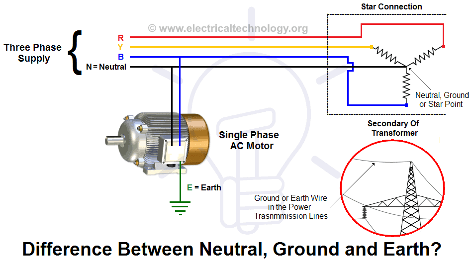
Neutral is the return path for electric current in an electric circuit which is intended to carry current in normal condition. This current may result from various factors, primarily due to phase current imbalances and occasionally as a result of the presence of 3rd and 5th harmonics.
The neutral wire provides a return path for the current to flow back to the power source, completing the circuit. In household wiring, it usually carries current from various electrical loads back to the electrical panel or distribution point.
In a properly functioning electrical system, the voltage on the neutral wire should be close to zero volts. It helps stabilize the voltage and maintain a relatively constant potential difference between the live (hot) and neutral wires.
The neutral wire is designed to carry current under normal operating conditions. If there is an imbalance between the current on the live (hot) wire and the neutral wire, it can indicate a fault or short circuit, which can be detected and used to shut off power for safety reasons.
There may be other reasons too but the magnitude of this current is in fraction of phase current and in few cases it can be even double of phase current. So Neutral wire is always assumed to be charged (in active circuit). This neutral wire is connected to the ground (by grounding as in a domestic power supply the Ground is bonded to Neutral, to provide a return path to the transformer at the sub-station) to make the second terminal of neutral wire at zero potential.
Earth or Ground
Earth or Ground is used for safety purposes to divert leakage or residual currents in the system through the path of least resistance. While Phase and Neutral are connected to the main power wiring, the earth may be connected to the body of equipment or to any system that, under normal conditions, doesn’t carry current. However, in case of insulation failure, it is designed to carry a minor current.
This current does not directly originate from the Live or Phase (Line or Hot) wire but instead comes from secondary connections that are not in contact with the live system under normal conditions. This current is typically much lower than the main Line or Phase current, often on the order of milliamperes (mA). However, this leakage current is still capable of causing electrocution or posing a fire risk with potentially severe damages. To mitigate these risks, such current is provided with a low-resistance path and directed to the earth via the ground/earth wire.
Due to differences in their applications, we never mix the grounding of Neutral and Earth. Nonetheless, both are grounded (although the methods may differ). If they were to be mixed, the earth wire, which is not supposed to carry any current under normal conditions, may accumulate charges and become a hazard
Difference Between Earthing and Grounding.
There is no difference between ‘Earthing’ and ‘Grounding‘; these terms are used interchangeably.
Grounding, also known as Bonding, is the term commonly used for earthing in North American standards such as IEEE, NEC, ANSI, and UL, while Earthing is the term used in European, Commonwealth countries, and British standards such as IS and IEC.
In simple words, Earthing and Grounding are synonyms. Both are similar words used for the same thing,
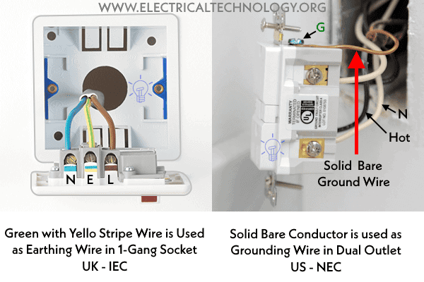
In the United States, according to NEC regulations, solid bare conductors are typically used for grounding purposes, such as Equipment Grounding Conductors (EGCs), Grounding Electrode Conductors (GECs), and bonding conductors. In contrast, under IEC standards, green or green-with-yellow-stripe insulated conductors are used for earthing.
Premium Resources about Electrical Grounding & Earthing – NEC & IEC
- Difference Between Grounding, Earthing and Bonding
- Difference Between AC Ground and DC Ground?
- Difference between Real Ground and Virtual Ground?
- Difference Between EGC and GEC in Electrical Grounding
- How to Size Equipment Grounding Conductor (EGC)?
- How to Size Grounding Electrode Conductor (GEC)?
- How to Size Earth Conductor, Earthing Lead & Earth Electrodes?
- How to Measure Ground Resistance? Testing Earth Resistance
- How to Measure Earth Loop Resistance Using Ammeter and Voltmeter?
- How to Measure Resistivity of Earth Using Wenner Method?
- How to Test the Earth Fault Loop Impedance – Various Methods
- How to Test Grounding / Earthing System using a Multimeter?
- How to Test Earthing & Grounding System using a Light Bulb?
- Why Doesn’t DC System Require a Grounding System Similar to AC System?
- Why is Copper Rod Used as Ground Rod in Grounding / Earthing System?
- Why is the Grounding Wire Bare and Not Insulated?
- Why is the Ground Wire Size Smaller than the Hot Wire?
- Why is the Ground Wire Always Positioned Above the Overhead Power Lines?
- Why Must Neutral and Ground Wires Be Bonded in the Main Panel?
- Why are Neutral and Ground Wires Separated in a Subpanel?
- Why is the Grounding Wire Bare and Not Insulated?
- Why Earth Pin is Thicker and Longer in a 3-Pin Plug?
- Why are Salt and Charcoal Added in Earthing Pit for Grounding?
- What is the purpose of Earth or Ground wire in overhead Transmission Lines
- What is Ground Rod and How to Install a Ground Electrode in Grounding System?
- How Do Grounding and Earthing Shoes Work to Prevent ESD?
- How Does the Grounding System Work in Aircraft & Submarines?
- Should You Connect GND and 0VDC? Combined AC & DC Grounding
- Can you Combine AC and DC Ground in a Solar Installation?
- Will I Get an Electric Shock If I Touch the Ground Wire?
- Design of Grounding / Earthing System in a Substation Grid
- Grounding and Methods of Earthing in PV Solar System
- Ground Terminal Up or Down: Which Way Should Outlets Face?
- Protective Multiple Earthing (PME) – TN-C-S – (MEN) and PNB
- What is Ground Resistance Tester – Working of Ground or Earth Tester


when doing a c.o.c for domestic wiring what are the values and how to do all the tests especially the pssc ,earth loop impendance
rennie
08/11/2015 at 5:56 pmwhen doing a c.o.c for domestic wiring what are the values and how to do all the tests especially the pssc ,earth loop impendance
Good page lets support it.
I WANT TO POWER THREE TRANSFORMER OF 1500KVA AT A DISTANCE OF 1000 METER FROM THE POWERHOUSE WHAT IS THE SIZE OF CABLE WILL I USED VOLTAGE IS 11KV TO BE LAY DIRECTLY UNDERGROUND OF +- 35C
I need to learn deep on domestic wiring and industrial wiring so help on notes and images
Difference between Domestic wiring and Industrial wiring, Domestic wiring is done either inside the conduit, under the roof, which is having closed/ limited air circulations, whereas industrial wiring is having enough Air circulation, because it installs in open atmosphere OR air changes which are keeping the wire temperature in control. If you are moving outside no need of fan is required, but as soon as entered in car/house, we needs to start fan/AC to keep the body temperature in limits.
Raise in continuous temperature, of wire effects directly to its life, and hence domestic wires are Class 2, having less conductor resistance, and higher current carrying capacity.
Whereas class 5 (Max no of strands, less Dia), is having high resistance than class 5, and limited cirrent carrying capacity than class 2.
Hello
good site…happy to find it. this will help s lot of young engineer.
good page i like it
Dear sir,
How r u, sir i want to know that i used the generator 250 kva on three phase. The problem is, the nuetral side of the generator show ampere. So how would i free my generator nuetral from current. Means what i do that my nuetral show 0 amp.
BALANCE YOUR LOAD ON 3 PHASES.IF LOAD IS EQUAL ON ALL PHASES THEN CURRENT WILL BE ZERO IN NEUTRAL CONDUCTOR.
tank u very much 4 all
I like this
Your graphic representation is very poor. There is no earthing /grounding shown of the transformer star point? Also the power supply to motor should show PE (Protective Earth conductor). Earthing of the motor frame is there only to avoid excessive touch voltages and not a positive return path for fault current. There is also no mention of PEN and N/PE conductors, 3 & 4 wire systems. Where Neutral and Protective conductors are combined into one or are separated.
Neutral ground use for transformer Neutral but must be separate from Normal Ground Grid.
Normal grounding grid for safety of Equipment & Humans Means Easy path to flow Electrones
Dear,
You are so many thanks to developed this website. This website is very helpful me. Again thanks to developer and other assistant.
what can cause generator set to burnt my equpiment in one of phase often
i have liked your page or site i have known more about wiring congrats
I recall that the standards in America (like NEC) were almost going to change “ground” with “earth” just to avoid confusion with the IEC standards in Europe, but they figured out that was not so easy, because ground and earth are different concepts and cannot be interchanged. Unfortunately, I cannot find that article any-more. Anyway, IEEE makes an important distinction between ground and earth. As you can read for example in “The Electronics Handbook, Second Edition”, the earth refers to mother earth, while ground refers to equipment grounding system. So, I would not go sooo easy to say that they can be interchanged because, even though I understand that in day-talk is not a big problem, when you start to deal with standards, it’s not a good idea to think that they are synonymous. At least, this is what I have understood.
great stuff
I’m a technical student so i am sincerely searching for many things that helps me to study my subjects . Now i am found a good place that easily helps me, to learn about my subjects
Thanks very much.Its very helpful…
wow!this is very nice&helpfull pages
THANK YOU ….
this is nice & helpfull pages
THANK YOU
good knololdge
Dear sir,
i want to know about the solar panel 25 kw,sir if are solar supply fail than,i ant that it automatically to cames to main supply and in the same way if main supply is failed than its come to generator supply.all are working on single phase.
sir came you explore how do are interlock tham.
distribution of load 3phase ; if load is not evenly distributed whats the effect w r t consumption etc.
hie gud people can u help with diagrams of electric motor i.e direct on line
Good. Basic diagram of star wound generator and distribution system. Here in Bulgaria it seems the generators are delta wound
The villages generally have no earth. Some electricians tie one phase (they call this phase null). The three phase supply cable does have four wires. The earth contacts in the sockets in our house is wired to the “phase null”. I have not found an electrician who can demonstrate how to identify the “phase null’at the sockets
I suspect the power generators here are delta wound. Could this be the case?
Why in single phase 220 volts and why in 3 phase 440 volts
Electronic technician
I have 190kv. Breaker burned. Any suggestions?
Oh wow! Your articles are very nice