Filters, Types of Filters and Their Applications
Different Types of Filters & Their Applications
Introduction to Filters
A frequency filter or also known as a frequency selective circuit is a special type of a circuit, which is used for filtering out some of the input signals on the basis of their frequencies.
A filter circuit passes some frequency signal’s without any attenuation (Reduction in amplitude) or with some amplification, & attenuate other frequency depending on the types of the filter.
Terms Used in Filters
To understand the frequency response of a filter, you need to have an idea about the terms used in it. Some of the terms used in describing the characteristics of a filter are given below;
Passband
The band of frequencies of the input signal that pass through the filter without any attenuation is called Passband. Usually, the Passband has no gain considering the filter is a passive filter. In active-filters, the passband may have some gain depending on the configuration of the circuit.
Passband lies before the cutoff frequency (mentioned below).
- Related Post: Types of Passive High Pass Filters
Stopband
The band of frequencies of the input signal that are blocked or attenuated in the filter is called Stopband. the gain at the stop is usually taken to be less than -3db of the input.
-3db gain is considered for the 1st order filter. 2nd order filter has -6db gain, which decreases with the order of the filter.
- Related Post: Types of Active Low Pass Filters
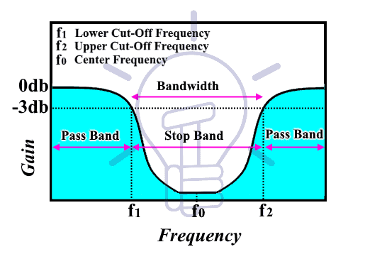
Cutoff Frequency
The passband & stopband are distinguished from each other by the cutoff frequency or corner frequency. The output signal’s voltage at the cutoff frequency is 70.7% of the input signal’s voltage. It is also known as “-3db frequency” because -3db represents half power. And it is the frequency where the power of the output signal becomes half the power of the input signal.
In a band pass or band reject filter, there are two cutoff frequencies.
-
Lower Cutoff Frequency:
The lower frequency at which the gain of the filter is half or -3db. It is denoted by f1. Bandpass filter allows frequency after this point, whereas the band stop filter blocks it.
-
Upper Cutoff Frequency
The upper frequency at which the output power is reduced by ½ of the input power. It is denoted by f2. Bandpass filter does not allow frequency after this point, whereas the band stop filter allows it.
- Related Post: Types of Passive Low Pass Filters
Center Frequency f0
The frequency that lies at the center of the passband or stopband in a bandpass filter or band reject filter respectively is called center frequency. It lies in-between the two cut-off frequency i.e. lower & Upper cut-off frequency. In fact, it is the arithmetic mean of both cut-off frequencies.
f0 = (f1 + f2) / 2
Bandwidth:
The range of frequencies that are passed (in case of bandpass filter) without any attenuation or the frequencies that are attenuated (in case of band reject filter) is called the bandwidth of the filter. The width of the frequencies before (in case of low pass filter) or after (in case of high pass filter) the cutoff frequency is called bandwidth
It is the difference between both cutoff frequencies of the band pass or band reject filter.
Β = f2 – f1
Roll-Off Rate;
It is the rate of change of gain/ output power, the drop rate of gain of the filter is called the roll-off rate. it is expressed as a gain loss per decade (ten times increase in frequency) or per octave (two-time increase in frequency).
The roll-off rate of nth order filter is 20n dB/decade or 6n dB/octave & n is the order of the filter. The per-decade means with a 10 times increase in frequency & the octave means a 2 times increase in frequency.
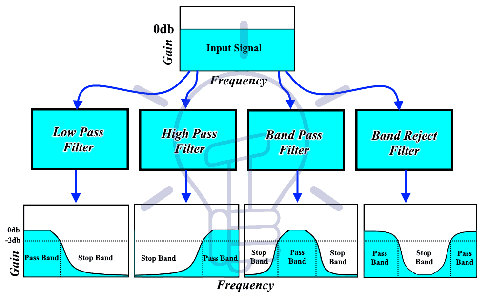
Types Of Filters:
There are different types of filters classified based on their frequency response and construction.
- Related Post: Types of Active High Pass Filter
Based On Their Construction:
According to the construction of the filters, there are two types of filters i.e. Passive Filters & Active filter.
-
Passive Filters
As the name suggests, passive filters are made up of passive components, such as resistors, capacitors & inductors.
It does not need any external source of energy. Therefore there is no voltage gain in these filters. The output voltage is always less than its input voltage.
It can easily filter a high-frequency signal but it cannot process any low frequencies.
Although its design is simple but connecting a load to this filter impacts on its characteristics. Cascading the passive filters for higher order filter affects the characteristics of the filter.
-
Active Filters
In addition to the resistor & capacitor, Active filter uses an active component such as an operational amplifier, transistors, etc.
The downside is that it needs an external source of power, but it provides a high voltage gain. This gain is used for amplifying any weak input signals.
The active filter can filter very low-frequency signals but it cannot process very high-frequency signal.
They may have a little bit of complex design but they provide very high input & low output impedance. That is why; the load impedance does not affect the characteristics of the active filters.
to increase the order of the filter, active filters are used in cascading configuration without worrying about the loss of input signals power.
- Related Post: Different Types of Sensors with Applications
Based On Their Frequency Response:
The filters are classified based on the frequency response into the following four categories.
-
Low Pass Filter.
Low Pass filter allow low-frequency signals without any attenuation (decrease in power) but it rejects any high-frequency signals.
The low pass filter has a reactive component, whose reactance varies with the input frequency. The variation in the reactance causes the voltage drop to increase or decrease inside the circuit. if the voltage drop is larger at the output, the signal will be passed, otherwise, it is rejected by the filter.
The passband & stopband frequencies are defined by the cutoff frequency of the filter.
Any frequency less than the cutoff frequency is passed without any attenuation. While any other higher frequency signal then the cutoff frequency will be blocked.
Related Post: Types of SSR Relays – Construction & Operation
-
High Pass Filter.
The type of filter that allows the high-frequency signals to pass without any attenuation in its amplitude & blocks (rejects) any low-frequency signal is called high pass filter.
Any signal with a frequency lower than the cutoff frequency of the filter gets blocked. While any signal with a frequency higher than the cutoff frequency passes with full amplitude.
Related Post: Types of Diodes and Their Applications
-
Band Pass Filter;
This type of filter allows a specific band of frequencies & blocks any other frequencies lower or higher than its passband frequencies.
This type of filter has two cutoff frequencies i.e. lower & upper cutoff frequency.
Bandpass blocks low frequencies & high frequencies, while allows the frequencies in between known as the passband frequencies.
Any input signal having frequency belonging to the passband frequencies will get passed without any attenuation.
Combining low pass filter & a high pass filter together in a cascade configuration will provide a bandpass filter.
The low pass filter will block high frequencies & the high pass will block low frequency. & they will pass the middle frequencies in between
Related Post: Types of Rectifiers and Their Operation
-
Band Reject Filter;
This type of filter attenuates the signal whose frequencies lies in a fixed band of frequencies.
It is also known as Band Stop filter or Notch Filter.
It works completely opposite to the bandpass filter. It allows low-frequency signal & high-frequency signals. But it does not allow a fixed band of frequencies in between.
It also has lower & upper cutoff frequencies. And any signals having frequency in-between these cutoff frequencies are rejected by the filter.
- Related Post: Counter and Types of Electronic Counters
Applications Of Filters:
Frequency filters have so many applications in our livelihood; some of these applications are given below;
- The tuner in radio: The bandpass filter in the tuner of the radio allows a fixed frequency to the output speaker.
- Treble & bass of the speaker: The bass has lower frequencies & treble has higher frequencies. They are separated using high pass & low pass filter and are separately routed to corresponding bass speaker & treble speaker for clear music.
- Anti-Aliasing: it is a low pass filter that filters out the high-frequency components from a signal before sampling. It prevents the aliasing component form being sampled.
- Notch Filter: they are band rejects filters with a narrow bandwidth that filter out any interfering signal.
- Power Supply Smoothing: The output of the power supply which is a rectifier has an AC ripple in it. These frequencies are filtered out using a low pass filter which results in smoothing the output signal.
- Noise suppression: They are used in communication systems for noise removal from the received signals.
Related Posts:
- Types of Amplitude Modulation (AM) – Advantages & Disadvantages
- Types of Modulation Techniques used in Communication Systems
- Types of Resistive Sensors – Transducer, Potentiometer & Strain Gauge


