Short Circuit Currents And Symmetrical Components
Short Circuit Currents And Symmetrical Components
(Manuel Bolotinha)
Short Circuit Faults and Currents
Short-circuits can occur phase-to-phase and phase-to-earth, mainly due to:
- Dielectric breakdown of insulating materials (ageing, severe overheating and overvoltages, mechanical stress and chemical corrosion are the main factors for dielectric breakdown)
- Decrease of creepage distance (the shortest path between two conductive parts – or between a conductive part and the bounding surface of the equipment – measured along the surface of the insulation)
- Decrease of safety distance
- Non-controlled partial discharges (corona)
When one or more of these situations occur a “solid” or “incipient”[1] contact between conductors of different phases or between a conductor and a metallic no-live part can be established, causing a short-circuit, which diagrams are shown in Figure 1. 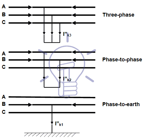
Figure 1 – Short-circuit diagrams
- Also read: Ammeter Connected in Short Circuit?
Phase-to-phase and phase-to-earth short-circuits may evolve towards three-phase short-circuit (the worst situation), due to dielectric breakdown caused by the high magnitude of currents.
Short-circuits cause thermal and electrodynamics stress on equipments and conductors.
Thermal stress is due to overheating of conductors (Joule law) and can cause dielectric breakdown and melting of metallic materials.
Electrodynamics stress is caused by the electromagnetic force, which is one of the four fundamental interactions in nature and it is described by electromagnetic fields that is defined by Lorentz law.
The value of this force is in direct proportion to the electric current value.
The calculation of short-circuit currents is used to design the installation and to define the characteristics of equipment, namely the breaking capacity of circuit breakers and the set-point of protection relays.
According to IEC Standard 60865-1 e 2 the equations to be used for the calculation of short-circuit currents are:
- Phase-to-phase:
- Three-phase
I”k3 = 1.1xUn / (√3xZd) – maximum
I”k3 = 0.95xUn / (√3xZd) – minimum
- Phase-to-phase
I”k2 = 1.1xUn / (2xZd) – maximum
I”k2 = 0.95xUn / (2xZd) – minimum
- Phase-to- earth:
I”k1 = 1.1xUn / (2xZd+Z0) – maximum
I”k1 = 0.95xUn / (2xZd+ Z0) – minimum
Definition of Symmetrical Components
All networks and equipments have internal impedance that can be split into three symmetrical components associated with the rotation of the electromagnetic field.
An unbalance system is divided into three separated symmetrical systems:
- Positive or synchronous sequence (Xd / Zd) – where the three fields rotate clockwise, with a phase displacement of 120°
- Negative sequence (Xi / Zi) – where the three fields rotate anti-clockwise, with a phase displacement of 120°
- Zero sequence (X0 / Z0) – a single fields which does not rotate, with each phase together (0° apart

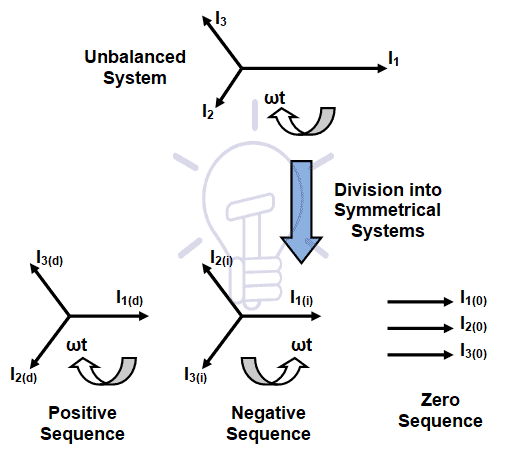
Figure 2 – Symmetrical components (currents)
Once the sequence networks are known, determination of the magnitude of the fault is relatively straight forward.
The ac system is broken down into its symmetrical components as shown above.
Each symmetrical system is then individually solved and the final solution obtained by superposition of these.
Positive, negative and zero sequence impedance data are often available from manufacturers.
A common assumption is that for non rotating equipment the negative sequence values are taken to be the same as the positive (Xd = Xi / Zd = Zi)
Zero sequence impedance values are closely tied to the type of earthing arrangements and do vary with equipment type.
While it is always better to use actual data, if it is not available (or at preliminary stages), the following approximations shown in Table 1 can be used.
Table 1 – Zero sequence impedance approximation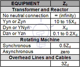
Equivalent Impedance of Equipment And Network Equivalent
The equivalent impedances of equipments and upstream network are:
Generators
- ZG = jX”d(Ω)xSn
Upstream network
- ZN = RN + jXN
- IZNI = 1.1xUn /√3xI”k3 or IZNI = 1.1xS”k3 /√3xUn2
- RN = 0.1xXN (empirical)
Transformers and reactors
- ZT=RT + jXT
- IZTI = uk(%)xUn2 /100xSn
- RT= Pcu/ 3xIn2
![]()
Motors
- ZM = jXM
- XM = Un/ ((Istart/In)x√3xIn
- I”kM = 1.1xUn/√3xXM
Cables
- ZC= ρ20°Cxl/s + j2πfxL
- RC = ρ20°Cxl/s
- XC = 2πfxL
![]()
Overhead Lines
For calculation purposes an overhead line may be represented by a “π diagram”, as shown in Figure 3.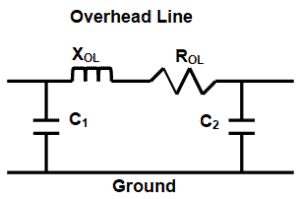
Figure 3 – π Diagram of an overhead line
In extra-high voltage (EHV) and high voltage (HV) overhead lines resistance of the line is usually negligible compared with the inductive reactance, but in low voltage (LV) and medium voltage (MV) overhead lines that resistance must be taken into account to calculate the impedance of the line.
For the calculation of short-circuit currents that do not involve faults to the ground th capacitive reactance is disregarded.
The equivalent positive (and negative) impedance of the line is calculated as follows:
- ROL = ρ20°Cxl/s
- XOL = 2πfxl1x(μ0/2π)x(ln (d/re)+(1/4n)) – single-circuit line
- XOL = 2πfxl1x(μ0/2π)x(ln (dxd’/rexd”)+(1/4n)) – double-circuit line

![]()
Total equivalent impedance
![]()
Legend
- S”k3: Short circuit power
- I”k3: Short circuit current
- Zd: Synchronous impedance
- Z0: Zero-sequence impedance
- Sn: Rated power
- Un: Rated voltage
- In: Rated current
- Z: Impedance
- ӀZI: Modulus of Z
- X: Inductance
- X”: Sub transient reactance
- R: Resistance
- ρ: Resistivity
- s: Conductor cross section
- l: Cable length
- l1: Overhead line length
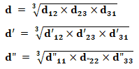
- d, d’, d”: Mean geometric distance between the three phase conductors of the line(s).
- d12, d’12: distance between conductors of phases 1 and 2 (line 1 and line 2)
- d23, d’23: distance between conductors of phases 2 and 3 (line 1 and line 2)
- d31, d’31: distance between conductors of phases 3 and 1 (line 1 and line 2)
- d”11, d”22, d”33: distance between conductors of phase 1 (2 and 3) of line 1 and line 2
- re: Equivalent radius for bundle conductors
- n: Number of strands in bundle conductor
- μ0: Space permeability – 4πx10-4 H/km
- ln: natural logarithm
- L: Inductance
- uk: Transformer impedance voltage drop
- Pcu: Transformer resistive losses
- f: Frequency
![]()
You may also read:


Good app but need pdf download to study ..plz an also option to download pdf