EMF Equation of a Transformer
Transformer’s EMF Equation
The magnitude of the induced electromotive force (EMF) or voltage in a transformer can be determined by the EMF equation of the transformer. When a source of alternating current (AC) is applied to the primary winding of the transformer, known as the magnetizing current, it produces alternating flux in the transformer’s core.
The produced alternating flux in the primary winding of the transformer becomes linked with the secondary winding through mutual induction. Since it is alternating flux in nature, there must be a rate of change of flux, according to Faraday’s law of electromagnetic induction, which states that if a conductor or coil is linked with any changing flux, there must be an induced EMF in it.
The same happens in transformers as well as induction motors as induction motor is fundamentally a transformer.
- Related Post: Power Transformers Maintenance, Diagnostic & Monitoring
EMF Equation of Electrical Transformer
Now, let’s learn how to determine the magnitude of the induced EMF in a transformer using the transformer’s EMF equation.
Lets,
- N1 = Number of turns in primary windings.
- N2 = Number of turns in second windings.
- Φm = Maximum flux in the core in Weber = (Φm = Bm.A)
- f = Frequency of A.C input in Hz.
Related Post: EMF equation of an Alternator or AC generator
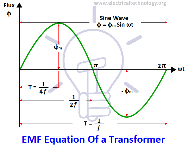
As shown in the fig above, the flux increases from its zero value to the maximum value Φm in one quarter of the cycle, i.e. in ¼ second.
Average rate of change of flux = [ Φm / (¼ f.)]
= 4f Φm Wb/s or volt
Now rate of change of flux per turn means induced EMF in volts.
Average EMF / per turn = 4f Φm volt.
If the flux Φm varies sinusoidally, then RMS value of induced EMF is obtained by multiplying the average value by the form factor.
Form Factor = RMS value / Average value = 1.11
RMS value of EMF / turn = 1.11. 4f Φm= 4.44f Φm volt
Now, consider the RMS value of the induced EMF across the entire primary winding.
= ( induced EMF / turn) x number of primary turns
E1 = 4.44 x f x N1 Φm ……….. (i)
E1 = 4.44 xf N1 Bm A … [as (Φm = BmA)]
Similarly, the RMS value of the EMF induced in the secondary winding is,
E2 = 4.44 x f N2 Φm ……….. (ii)
E2 = 4.44 x f N2 Bm A. … [as (Φm= BmA)]
It’s seen from (i) and (ii) that: EMF Equation of the Transformer =
E1 / N1= E2 / N2 = 4.44 x f Φm. …… (iii)
It means that EMF / turn is the same in both the primary and secondary windings in the transformer i.e. flux in Primary and Secondary Winding of the Transformer is same.
Moreover, we already know that from the power equation of the transformer, i.e, in ideal Transformer (there are no losses in transformer) on no-load,
V1 = E1
and
E2 = V2
Where,
- V1 = supply voltage of primary winding
- E2 = terminal voltage induced in the secondary winding of the transformer.
Related Post: Transformers Fire Protection System – Causes, Types & Requirements
Voltage Transformation Ratio (K)
As we have derived from the above EMF equation of the transformer (iii);
E1 / N1= E2 / N2 = K
Where,
K = Constant
The constant “K” is known as voltage transformation ratio.
- If N2 > N1, i.e. K > 1, then the transformer is known as a step-up transformer.
- If N2 < N1, i.e. K < 1, then the transformer is called step-down transformer.
Where,
- N1 = Primary number of turns of the coil in a transformer.
- N2 = Secondary number of turns.
Power Equation of the Transformer
We have already discussed it in our previous post which can be seen it here.
Related Posts:
- Transformer Efficiency, All day Efficiency & Condition for Maximum Efficiency
- Can we operate a 60HZ Transformer on 50Hz Supply Source and Vice Versa?
- Which Transformer is More Efficient When Operates on 50Hz or 60Hz?
- How to Calculate the Rating of Transformer in kVA (1 Phase and 3 Phase)?
- Current Transformers (CT) – Types, Characteristic & Applications


It is really easy to understand the emf equation of a transformer. It is even easier to understand with the neat and clean diagram. Just like this post <a href="http://www.electricaleasy.com/2014/03/electrical-transformer-basic.html" rel="nofollow"> Electrical Transformer</a>. Thanks for the post. :)
How we find numerical question in this site.please tell me
Wonderful job. Keep it up, but add some MCQ question.