Binary Decoder – Construction, Types & Applications
Digital Binary Decoder – Types & Construction
What is Binary Decoder?
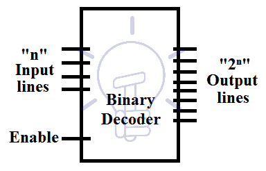
A digital combinational circuit used for converting “n” bits of binary number into a combination of “2n” or less unique and separate output lines is called digital decoder or binary decoder. In simple words, Binary Decoder used to decode a Binary Codes and it is the reverse of Binary Encoders.
There is an enable input which can enable and disable the whole circuit. Enable can be active high and active low. Active high; when enable input is high the decoder is enabled when its low the circuit is disabled. Active low; when enable input is low the decoder is enabled.
 It actually converts coded information in one format to another format. In other words, the data may be decoded by decoders same like data encoded by encoders in term of reverse operation. A decoder generates min-terms. Min-terms are products of the input, which means that decoder is made up of AND gate and NOT gates. It can be designed with NAND gate considering the output of the decoder will be invert of AND gate decoder.
The quantity of AND gates used is equal to the number of output lines (min-terms). The NOT gate is used for inverting each input lines so the quantity of NOT gates depends on input lines.
Each minterm is associated with a unique set of binary inputs when that specific combination of binary input is applied to the decoder the concerned output is set to high or low depending on the gate(AND, NAND) used.
Types of Decoders
Some of the Line decoders are given below with details.
- 2-to-4 Line Binary Decoder
- 3-to-8 Line Decoder
- 4-to-16 Line Decoder
Also read: Counter and Types of Electronic Counters
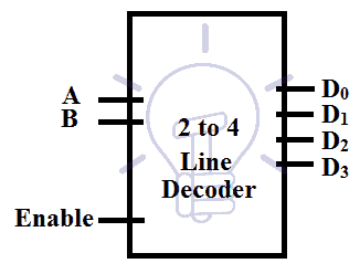
2 to 4 Line Decoder
This decoder has 2 input lines and 22 = 4 output lines. The input is in binary format so there will be 4 possible combinations of input and for each of these combinations, there is a separate output line which goes high or low when these inputs are applied. There is an active high enable input which can enable and disable the whole decoder.
Construction of 2 to 4 Line Decoder using AND Gate
In this decoder, for a specific binary input combination, the specified output line gives “1” and all the other output lines become “0”. Schematic of 2 to 4 Line Decoder Using AND Gate is given below after truth table.
Truth Table
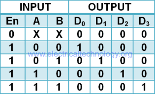
The truth table of 2 to 4 line decoder using AND gate is given below:
En is enable bit and A, B are input lines. D0 – D3 are output lines.
According to the truth table of “2 to 4 line decoder”, the expression for output is
D0 = A̅B̅ = m0, D1 = A̅B = m1, D2 = AB̅ = m2, D3 = AB = m3
To implement these expression we need two NOT gates and 4 AND gates for each Min-term as shown in the figure below.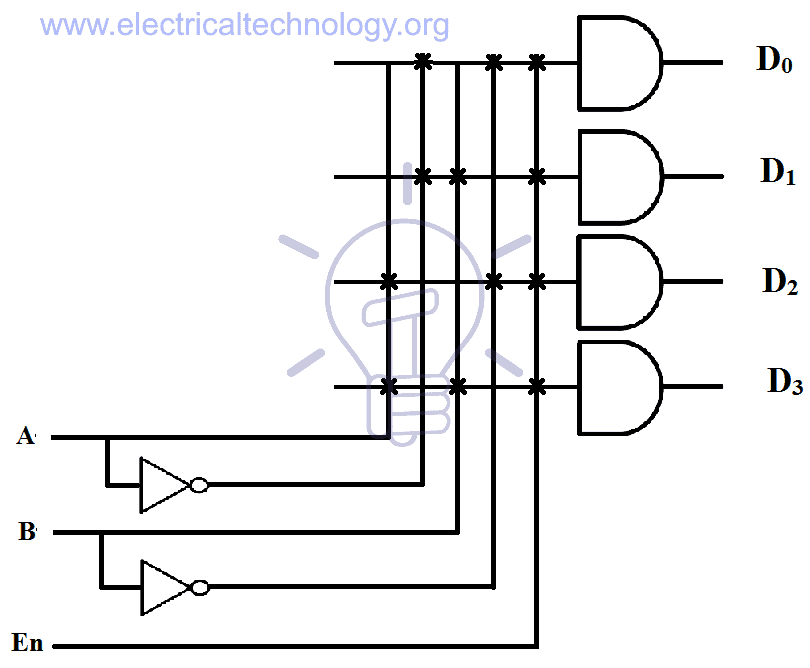
As you can see, each of these outputs represents a min term m0, m1, m2, m3 which makes it easy to implement any Boolean function with 2 variables. En is applied to every AND gate whenever En = 0, all output lines will be 0.
Example:
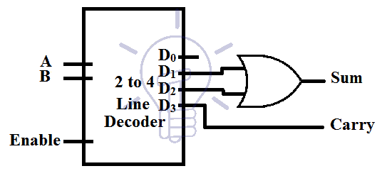
Half Adder Implementation Using Decoder
Half adder Boolean function can be implemented with 2-4 line decoder.
Sum = A̅B + AB̅ = ∑(m1+m2)
Carry = AB = m3
Thus the 2nd and 3rd output of decoder will be ORed (sum) to form Sum and the 4th output will be Carry as shown in the figure below.
Construction of 2 to 4 Line Decoder Using NAND Gates
NAND gate is invert of AND gate so using NAND gate instead of AND gate in decoder will invert the output of the decoder. For a specific combination of the input signal, a separate output line will give “0” instead of 1 and all other outputs will be “1”.
Truth Table
The truth table of 2-4 line decoder using NAND gate is given below. En is enable bit and A, B are input lines. D0-D3 are output lines.

According to the truth table the expression for output will be;
D̅0 = A̅B̅, D̅1 = A̅B, D̅2 = AB̅, D̅3 = AB
Implementation of these expression using NAND gates is shown in the figure below. 4 NAND gates and 2 NOT gates are used.
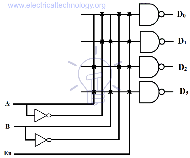
This decoder produces “0” on a separate output line, for a specific binary input combination.
3 to 8 Line Decoder
This decoder has 3 binary inputs and 8 output lines. 3 binary inputs mean there are 8 different combinations of inputs and for each combination of input, there is a separate output line to respond.
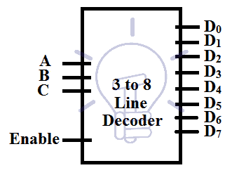
It is also known as binary to octal decoder because it converts binary format into octal number where each output line represents a number in the octal system.
3 to 8 Line Decoder using AND Gates
For a specific input combination, a single output line goes “1” and all other outputs become “0”. Schematic diagram of 3 to 8 Line Decoder using AND Gates is given below right after truth table.
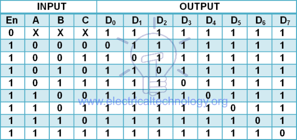
Truth Table
The truth table of 3 to 8 line decoder using AND gate is given below. En is enable bit and A, B, C are input lines. D0-D7 are output lines.
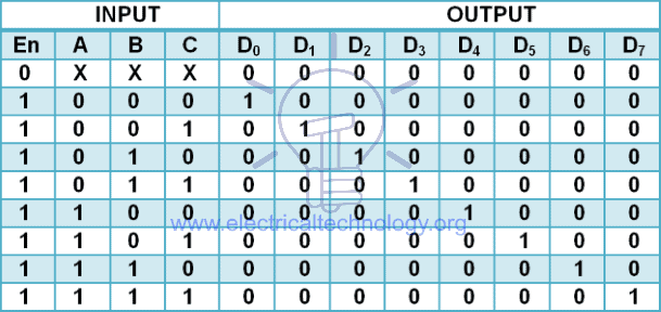
According to the truth table, the output expression is:
D0 = A̅B̅C̅ D1 = A̅B̅C D2 = A̅BC̅ D3 = A̅BC
D4 = AB̅C̅ D5 = AB̅C D6 = ABC̅ D7 = ABC
These expressions can be implemented using 8 AND gates and 4 NOT gates as shown in the figure below.
Each output represents a min-term and therefore it can be used to implement any Boolean function of 3 variables.
3 to 8 Line Decoder Using 2 to 4 Line Decoder
3 to 8 line decoder can be made with two 2 to 4 line decoder with enable inputs as shown in the figure below.
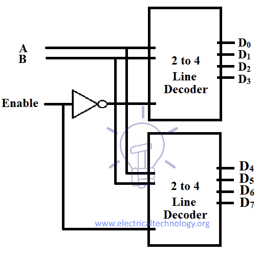
Enable En will be taken as the Input MSB, when En = 0, the upper decoder will be enabled and output D0-D3 will be generated based on the combination of input A, B. And when En = 1, then the lower decoder will turn on and output D4-D7 will be generated based on input A, B.
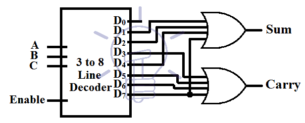
Implementation of Full Adder
A full adder can be implemented with a 3 to 8 line decoder. Full adder has 3 inputs Cin,A,B and 2 output Sum and Carry. The SOP expression for sum and carry is
Sum = C̅in A̅B + C̅in AB̅ + Cin A̅B̅ + Cin AB = ∑( m1 + m2 + m4 + m7 )
Carry = C̅in AB + Cin A̅B + Cin AB̅ + Cin AB = ∑( m3 + m5 + m6 + m7 )
Thus the specified min-terms (output) of the decoder will be ORed (sum) together to form Full adder as shown in the figure below:
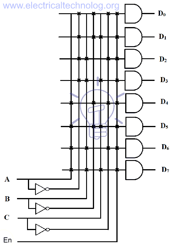
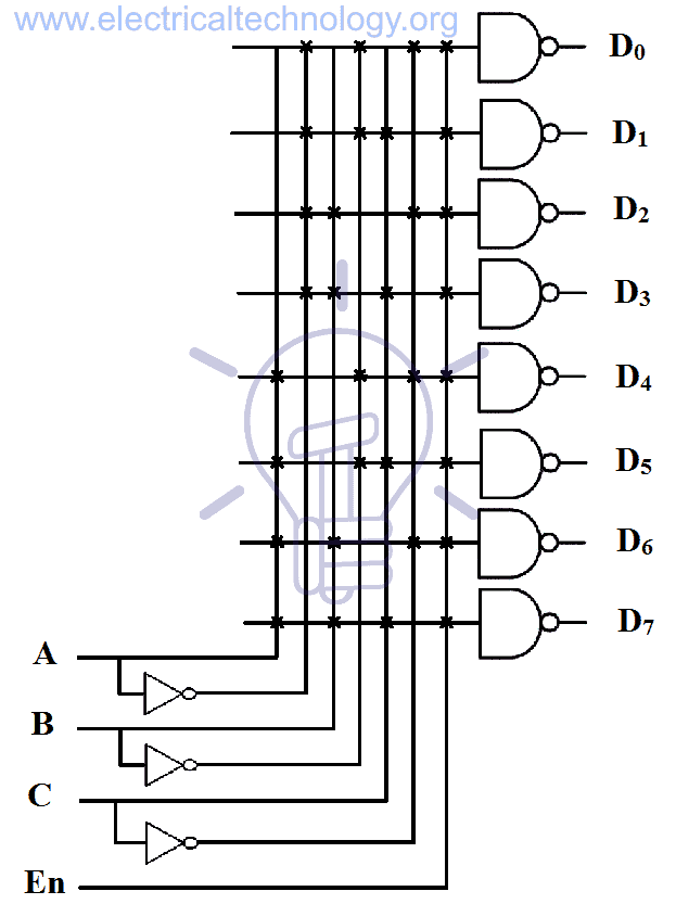
3 to 8 Line Decoder using NAND Gates
For a specific combination of 3-bit binary input, a single out of 8 output lines will give “0” and all other output lines will produce “1”.
Truth Table
The truth table of 3 to 8 line decoder using NAND gate is given below. E is enable bit and A, B, C are input lines. D0-D7 are output lines.
According to the truth table of 3 to 8 line decoder, the Boolean expression for is:
D̅0 = A̅B̅C̅ D̅1 = A̅B̅C D̅2 = A̅BC̅ D̅3 = A̅BC
D̅4 = AB̅C̅ D̅5 = AB̅C D̅6 = ABC̅ D̅7 = ABC
These output expressions can be implemented using 8 NAND gates and 4 NOT gate as shown in the figure below.
Binary Decoder IC Configuration & Pinouts
This is NAND gate based IC. A single output line will give “0” on a unique binary input combination.
The inputs to the IC are C, B, A. Enable G̅L̅ is known as Latch-enable. When it goes from low to high it stores the input data and provides output corresponding to the stored input, ignoring the upcoming changes in the input data as long as G̅L̅ is high. When G̅L̅ is low then the input is not stored
The decoder will give output only and only when G̅2̅ and G1 are set LOW and HIGH respectively otherwise all output lines will be HIGH state “1”.
74137 TTL 3 to 8 Line Decoder with Pin Configurations
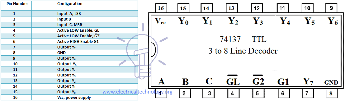
Pin Configuration of IC 74137 TTL 3 to 8 line decoder.
| Pin Number | Configuration |
| 1 | Input A, LSB |
| 2 | Input B |
| 3 | Input C, MSB |
| 4 | Active LOW Enable, G̅L̅ |
| 5 | Active LOW Enable, G̅2̅ |
| 6 | Active HIGH Enable G1 |
| 7 | Output Y7 |
| 8 | GND |
| 9 | Output Y6 |
| 10 | Output Y5 |
| 11 | Output Y4 |
| 12 | Output Y3 |
| 13 | Output Y2 |
| 14 | Output Y1 |
| 15 | Output Y0 |
| 16 | Vcc, power supply |
Applications of Binary Decoders
Binary decoders are widely used in digital electronics systems. Some common application and uses of decoders are as follow:
- It is used as binary to decimal decoder.
- It is used as address decoder in memory systems of computer and CPU memory location identifications..
- It is also used as instruction decoder in the control unit of Central Processing unit (CPU).
- They can also be used to make half adder and full adder.
- Decoders are also used to select different task for memory in microprocessor memory systems, select different devices in microprocessor input / output, enable different functions units in microprocessor instruction decoding, enable different rows and block of memory depending on address in memory chips.
- Decoders are used in seven segment displays as well as data demultiplexing.
You may also read:


hello
in the k’map of out put C . is have problem .
the sepration is wrong because it lost to drow 1 Colum
it should has drow two colum