Busbars and Connectors in HV and EHV installations
Busbars and Connectors in Indoor & Outdoor Installations
What is Electric Busbar?
A conductor or group of conductor used to collect the power from incoming feeders and distribute to the outgoing feeders is known as busbar. In other words, Busbar is a junction where the incoming and outgoing feeders current meets i.e. it collects the power at single point.
Busbars for Outdoors Installations
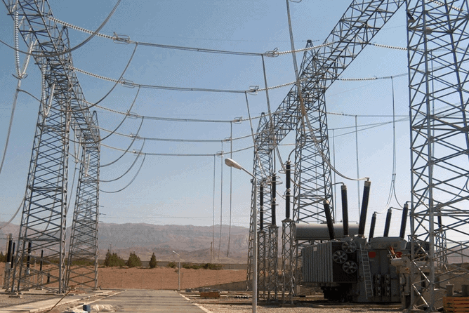
In HV and EHV installations and in outdoors MV installations bare busbars and connectors are used and the conductors may be tubular or stranded-wires.
Tubular busbars are supported by column insulators (usually ceramics) and stranded-wires are tight with dead end clamps.
Figures 1 and 2 show examples of what was explained above.

Busbars for switchgear installations are made either of copper or aluminium and its alloys (Al-Mg-Si – aluminium – magnesium – silicon).
The main characteristics of bare busbars are:
- Diameter (tubular conductors) and cross-section (stranded-wires).
- Mechanical strength and parameters (tensile, compressive, bending and buckling strength; moments of resistance and inertia).
- Rated current.
Taking into account that these conductors are non-isolated rated voltage is not to be considered.
For the connection of busbars to equipments terminals proper connectors must be used, like those shown in Figure 3.
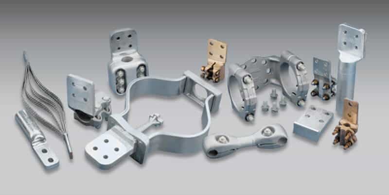
For copper-copper connections connectors are made of bronze; for aluminium – aluminium connections aluminium Alloy connectors shall be used; for copper-aluminium connections bi-metallic connectors must be used, to avoid corrosion caused by electrolytic effect.
Insulated Busbars & Trunking Systems
In indoors MV and LV installations, namely with high currents and space available is low, busbars may be surrounded by enclosures, normally metallic, for mechanical protection and insulation purposes.
This solution reduces the bus bar heat dissipation due to reduction in cooling air flow and radiation losses and therefore gives current ratings which may be considerably less than those for free air exposure. To minimize current reduction ventilated enclosures may be used.
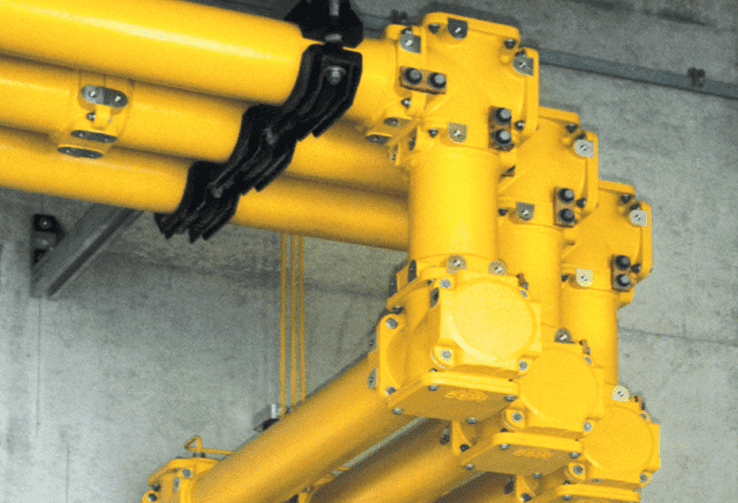
Figure 4 shows an example of an enclosed busbar.
In isolated busbars, usually made with copper or aluminium flat bars (one or more per phase, depending of the current), each individual phase or pole is surrounded by a separately earthed sheath which is connected at its ends by a full short-circuit current rated bar.
The sheath is intended primarily to prevent inter-phase short-circuit currents developing. They have the further advantage that the high magnetic fields created by the conductor current are almost completely cancelled by an equal and opposite current induced in the enclosure or sheath.
Common insulating materials are air and SF6.
In LV installations one economic method for power distribution, and to provide supply to several equipments and interconnections between switchboards or switchboard and transformer, is the use of a trunking system, as shown in Figure 5.
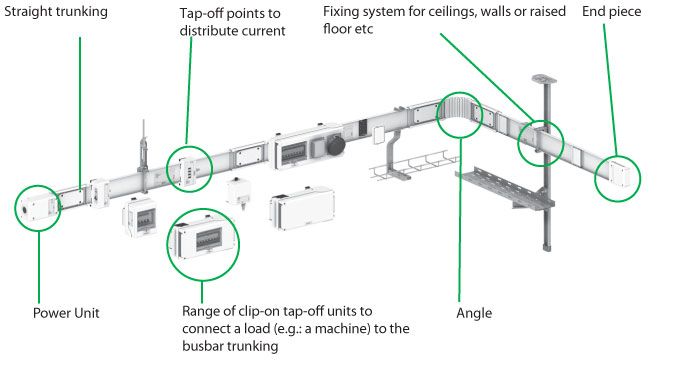
A trunking system is a pre-assembled set of flat bars conductors (phase(s) and neutral) within a single metallic enclosure.
In feeder trunking systems power is taken from busbar trunking by the use of tap off units which connect at defined positions along the busbar trunking, and allow power to be taken from the system, usually via a suitable protective device.
Trunking systems present advantages over cables:
- More economical to use and easier to install, particularly for the higher current ratings, where multiple single core cables are used to achieve the current rating and compliance with voltage drop and voltage dip requirements. Beside this, bunch of cables are increasing possibility of heating between cables and eventually short circuit.
- Greater mechanical strength over long runs with minimal fixings resulting in shorter installation times.
- Replaces multiple runs of cable with their associated supporting metalwork.
- Less termination space required in switchboards.
- Cable jointer not required.
- Multiple tap-off outlets allow flexibility to accommodate changes in power requirements subsequent to the initial installation (subject to the rating of the busbar trunking).
- Repositioning of distribution outlets is simpler.
- System is easily extendable.
- Aesthetically pleasing in areas of high visibility.
- Busbar trunking systems may be dismantled and re-used in other areas
Busbar trunking systems provide a better resistance to the spread of fire