Design and Installation of EHV/EHV and EHV/HV Substations
Types and Configurations of EHV/EHV and EHV/HV Substations
The Role of EHV/EHV and EHV/HV Substations in Transmission Network
EHV/EHV and EHV/HV[1] substations are an important element of the electricity transmission network of a country or of a large area of a country and their functions are:
- Interconnection of power plants of the national or area electrical grid.
- Step up and step down voltage of the distribution network to suitable values for networks operating conditions.
- Spread along the country or along an area of a country of EHV and HV overhead lines, submarine cables and underground cables.
- Electrical power supply of HV/MV[2] distribution substations.
Figure 1 shows a schematic diagram of the electrical grid where it is represented power plants, substations, transmission lines and distribution lines (MV and LV[3]).
- You may also read: What Exactly Is A Smart Grid?
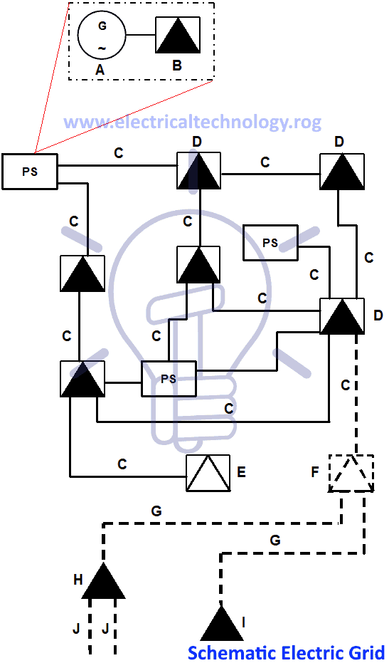
Figure 1 – Schematic diagram of an electrical grid
Some consumers (industry, shopping malls, casinos, etc.) that require high power supply are connected to EHV, HV or MV networks and have their own substations (private substations – EHV/HV, HV/MV or MV/LV).
EHV And HV Equipments
Main EHV and HV equipments of substations, apart from busbars and insulators, are:
– EHV/EHV and EHV/HV power transformers – to step down or to step up the voltages of the network.
– Circuit breakers – for the interruption service currents and short-circuit currents and to extinguish electric arc that is formed when an electrical current is interrupted such as Air Circuit Breaker, Miniature Circuit Breaker, ELCB, RCD etc.
– Isolators – to isolate a part of the installation, ensuring that isolation is visible what is vital for personnel safety.
– Instrument transformers (voltage – VT – and current – CT) – to provide an image of voltage and current to metering equipment, protection units and control and monitoring systems.
– Surge arresters – for the protection of equipments against overvoltages (lightning and switching overvoltages).
– Neutral-earthing reactors – for neutral grounding of transformers and networks to limit the phase-to-earth short-circuit current.
– Current-limiting reactors – to limit three phase and phase-to-phase short circuit currents, allowing reducing the short circuit withstand values of equipments and busbars.
– Shunt reactors – to compensate capacitive currents that have an origin in long underground cables.
– Capacitor banks – to compensate inductive currents that have an origin in long overhead lines.
Types of EHV/EHV And EHV/HV Substations
EHV and HV substations are usually installed outdoors with the equipments seated at metal or concrete structures; connections are made using bare cables or round section bars (aluminium or aluminium alloy) and the incoming and outgoing feeders are overhead lines, connected to concrete or metal lattice towers, or underground cables. This type of substation is designated by AIS – Air Insulated Substation.
They are organized by “bays”, being the following the more usual:
- Line bay
- Transformer bay
- Bus coupling bay
- Reactors bay (neutral-earthing reactors; current-limiting reactors; shunt reactors)
- Capacitor bank bay (usually only in HV)
Figure 2 shows an example of equipment layout in an AIS substation.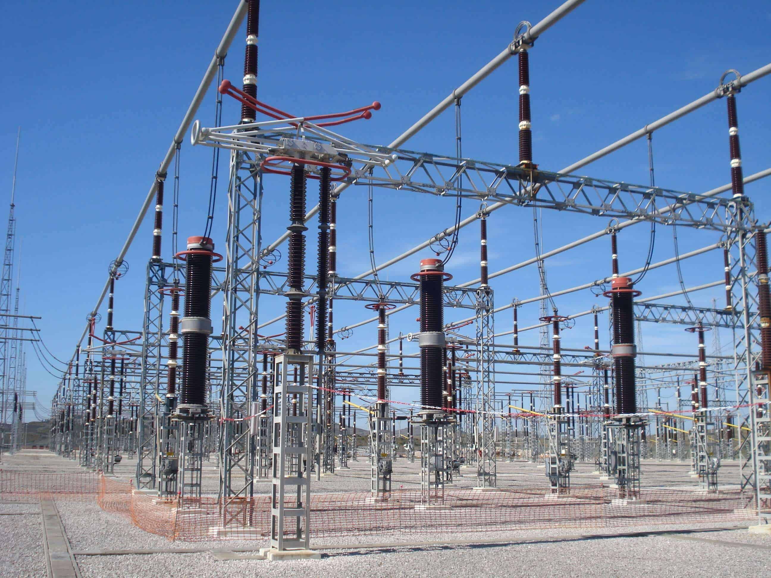
Figure 2 – Equipment layout in an AIS substation
When the space available for the installation of the substation is short or when the environmental conditions are extremely severe the usual solution is to install a GIS – Gas Insulated Substation, which schematic diagram is shown in Figure 3. This equipment is a compact multicomponent assembly, enclosed in a ground metallic housing, which the primary insulation medium is a compressed gas – sulfur hexafluoride (SF6) – and it must be in accordance with IEC Standard 62271.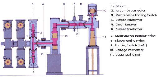
Figure 3 – GIS bay schematic diagram
Main advantages of this solution are:
- Easy maintenance
- Lower erection time and cost
- Non- flammability and non-explosive
- Oil-free and less pollution
GIS are usually installed indoors (Figure 4), although there are outdoors installations (Figure 5).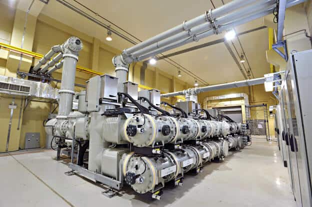
Figure 4 – Indoors GIS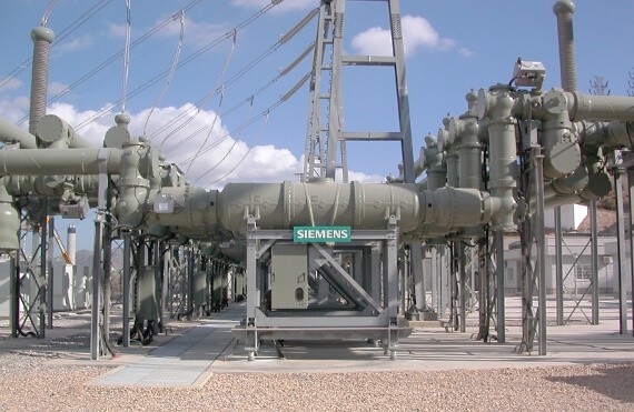
Figure 5 – Outdoors GIS
Another common solution, when the space available is short, is the installation of the designated as “hybrid” equipment – circuit breaker, isolators and instrument transformers are pre-mounted, at the manufacturer facilities, in a metallic enclosure; SF6 insulated, as represented in Figure 6.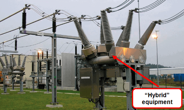
Figure 6 – Hybrid equipment
Main advantages of this solution are:
- Reduction of required installation area (see Figure 7).
- Reduction of civil construction works.
- Reduction of erection time.

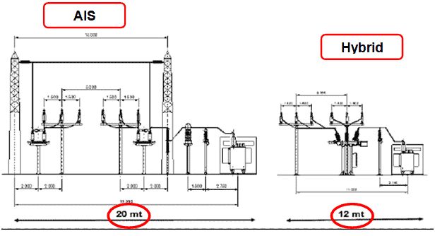
Figure 7 – Comparison of required space between AIS and hybrid substations
- You may also read: Fault Current Limiter and Their Types
Common Configuration of EHV/EHV and EHV/HV Substations
EHV/EHV and EHV/HV substations may have several configurations (topologies), depending on the requirements of the continuity, the reliability and the quality of power supply. The same substation may have more than one type of configurations, depending of the voltage levels.
The more usual configurations, shown in the single line diagrams of Figures 8 to 11, are:
- Single busbar.
- Double busbar, with or without “bus coupling bay”.
- One circuit breaker and a half.
- Triple busbar.
 Figure 8 – Single busbar configuration
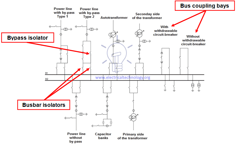
Figure 9 – Double busbar configuration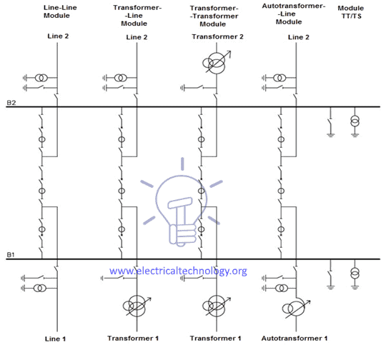
Figure 10 – One circuit breaker and a half configuration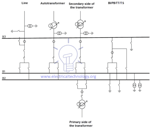 Figure 11 – Triple busbar configuration
Single Busbar Configuration
it is the simplest and it is used in small substations, not very important, where the continuity of power supply is not prevailing as shown in fig 9.
Double Busbar Configuration
It is used in substation where the division of bays between the two busbars and the possibility to change bays to one busbar to the other are operations that allow increasing the continuity and the reliability of power supply, minimizing the number of bays out of service when the breaker failure protection actuates as shown in fig 10.
With this configuration, if there is a bus coupling bay and the line and transformers bays have a bypass isolator is possible to keep the continuity of power supply when there is a fault in the circuit breaker or it is breaker maintenance operations are necessary.
One Circuit Breaker and a Half Configuration
this configuration allows better reliability of the network and flexibility of operation, taking into account that if the breaker failure protection actuates the other bays are not put out of service. (fig 11)
This configuration is more expensive than the double busbar configuration and requires a more complex protection system, but maintenance costs are reduced.
Triple Busbar Configuration
With triple busbar configuration it is possible to execute maintenance operations on a complete bay, which is totally placed in bypass mode. (fig 12)
One circuit breaker and a half and triple busbar configurations are only used in EHV installations.
Complementary Installations Of EHV/EHV And EHV/HV Substations
Apart from equipments referred in chapter 2 and busbars and isolators, EHV/EHV and EHV/HV substations require the installations of the equipments and systems referred below:
– Earthing (or grounding) system, where all non-live metallic parts and the lightnining protection system must be connected: buried bare copper cable, earth rods and connectors (see Figure 12).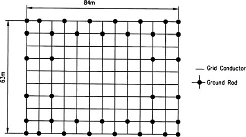 Figure 12 – Schematic layout of earthing system
For details, may read about Design of Grounding / Earthing System in a Substation Grid
– Lightning protection system: lightning rods and/or lightning protection wires (see Figure 13)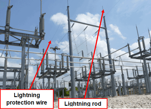 Figure 13 – Substation lightning protection
– LV AC auxiliary power supply (lighting, small power, etc.): auxiliary MV/LV transformer(s); emergency generator set; distribution switchboard(s).
– DC auxiliary power supply (usually 110 V) for control, monitoring and protection system and equipments: battery; charger; distribution switchboard(s).
– Control, monitoring and protection system
This system, which functions are performed by a set of equipments and sub-systems, has a topology (architecture) usually with 4 levels and is designated as DCS (Distributed Control System), as shown in Figure 14:
- Level 1: field devices.
- Level 2: local control units (IED – Intelligent Electronic Device; PCL – Programmable Control Units).
- Level 3: substation local control center (LCC).
- Level 4: remote control center (RCC), usually designated as SCADA (Supervisory Control and Data Aquisition).
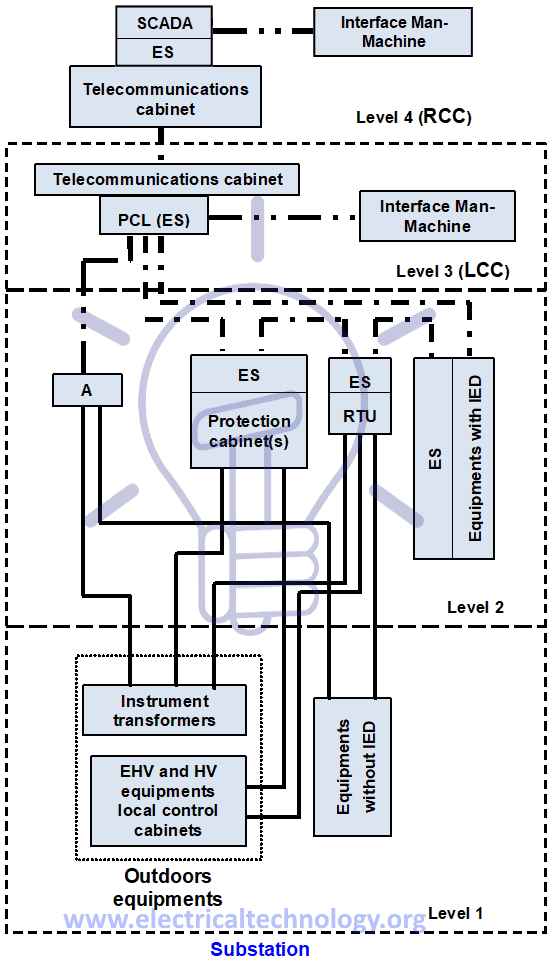
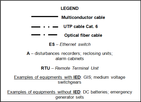
Figure 14 – Schematic typical architecture of substation control, monitoring and protection system
Under normal conditions local control is only possible with the authorization of the person in charge of the operation of the substation that must release this function to the assigned local operator.
The control of circuit breaker and isolators is made according to the defined interlocking programme.
The system usually performs the following control and monitoring actions:
- Circuit breakers and isolators control (opening/closing).
- Circuit breakers and isolators open/close status
- Circuit breakers synchronization.
- Control of tap changers and cooling system of power transformers.
- Reclosing
- Disturbance recording.
- Control and monitoring of LV AC and DC auxiliary power supplies.
- Metering (energy; voltage; current; power; frequency; power factor).
- Load shedding.
The control of circuit breaker and isolators is made according to the defined interlocking programme.
Common protections used in EHV/EHV and EHV/HV substations are indicated below (between brackets is shown their code in accordance with IEEE/ANSI/IEC[4] standards):
- Overvoltage (59)
- Undervoltage (27)
- Directional phase overcurrent (67)
- Directional earth overcurrent (67N/67G)
- Instantaneous phase overcurrent (50)
- Instantaneous earth overcurrent (50N/50G)
- Restricted earth fault overcurrent (64G)
- Time delay phase overcurrent (51)
- Time delay earth overcurrent (51N/51G)
- Overload protection (49)
- Overhead line distance protection (21)
- Overhead line/underground cable differential protection (87L)
- Transformer differential protection (87P)
- Bus bar differential protection (87B)
- Breaker failure (50 BF)
- Week End Infeed (21WI)
You may also read: Comparison between AC and DC Transmission System
For safety reasons the actuation of protection units is done directly to the tripping coils of the circuit breakers and should not be done through the PLC.
[1] EHV: Extra High Voltage (V ≥ 170 kV). HV: High Voltage (72,5 ≤ V ≤ 123 kV). The referred values of V are the highest voltage for equipments, according to IEC Standard 60038– IEC standard voltages. [2] MV: Medium Voltage (3,6 kV ≤ V ≤ 52 kV). [3] LV: Low Voltage (V ≤ 1 kV AC). [4] IEEE: Institute of Electrical and Electronic Engineers (USA). ANSI: American National Standards Institute (USA); IEC: International Electrotechnical Commission.
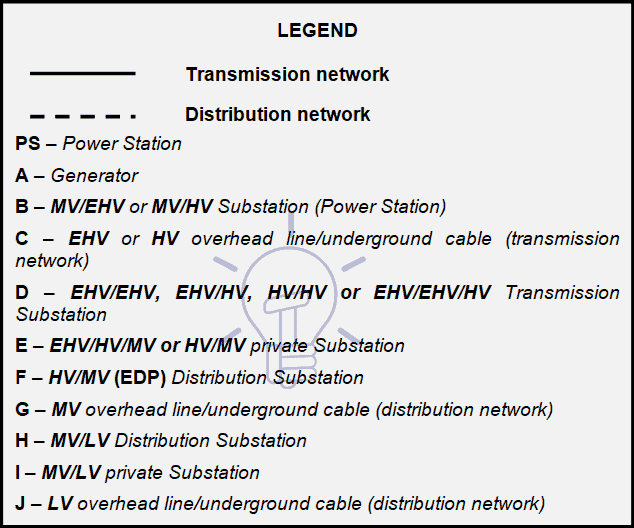
- LEGEND for Fig 1.
____________ Transmission Network
– – – – – – – – Distribution Network
PS – Power Station
A – Generator
B – MV/EHV or MV/HV Substation (Power Station)
C – EHV or HV overhead line/underground cable (transmission network)
D – EHV/EHV, EHV/HV, HV/HV or EHV/EHV/HV Transmission Substation
E – EHV/HV/MV or HV/MV private Substation
F – HV/MV (EDP) Distribution Substation
G – MV overhead line/underground cable (distribution network)
H – MV/LV Distribution Substation
I – MV/LV private Substation
J – LV overhead line/underground cable (distribution network)
_______________________________________________________
- LEGEND for Fig 14
______ Multiconductor cable
__ . . __ UTP cable Cat. 6
__ . __ Optical fiber cable
ES – Ethernet switch
A – disturbances recorders; reclosing units;
alarm cabinets
RTU – Remote Terminal Unit
Examples of equipments with IED: GIS; medium voltage
switchgears
Examples of equipments without IED: DC batteries; emergency
generator sets
- You may also read: Power distribution in industries.