Cables Feeder Protection – Faults Types, Causes & Differential Protection
Cables Feeder Protection – Overcurrent & Differential Protection
Common Types of Faults
Common failure modes and faults of cables are:
- Electrically induced failures
- Mechanically induced failures
- Thermally induced failures
- Metallic (semiconducting) shield damage
- Poor Metallic Shield Contact
Explanation of each fault is follow respectively.
Electrically induced failures
These involve lightning, switching surges, and partial discharges.
Partial discharges may be caused by poor insulation system design or by manufacturing defects.
Mechanically induced failures
A mechanically induced failure can occur during installation due to use of excessive pulling tension and/or exceeding minimum bending radii.
Cable can also be damaged during construction when earth moving equipment can dig into the cable or cable duct banks such as in submarine cables.
Repeated bending and twisting during installation or in service can result in irreversible straining of conductor wires.
Thermally induced failures
Thermal degradation causes the insulation of the cable to lose its physical properties and they are due to overloading beyond its design capability for extended periods and/or excessive ambient temperature conditions.
Metallic (semiconducting) shield damage
This failure mode describes where the shield ceases to perform its function.
In order for the shield to perform its function, its volume resistivity must always remain sufficiently low. However, when metallic shield is damaged or corroded its volume resistivity is impacted by temperature.
At higher temperatures, the volume resistivity of the metallic shield increases significantly (due to peak loads, unbalance currents, or circulating currents) giving rise to high voltage gradients at sharp metal edges that will lead to corona effect / discharge and arcing damage (from outside in).
Corona and arcing will lead to eventual cable insulation failure.
Poor Metallic Shield Contact
This is the case where metallic shield is insulated from the semiconducting tape shield because of poor contact, what can be caused by a layer of corrosion or scale buildup on the metallic shield.
Such a condition will give rise to a potential difference between the semiconducting shield and the metallic shield that will cause arcing between the two shields.
This will lead to arcing damage from the outside into semiconducting shield and insulation and eventual cable failure, being more severe if there are multiple areas of poor contact or breaks between the two shield systems.
Failures in most cases occur at the end-terminations or joints (where the factory-manufactured insulation gets disturbed).
Related articles:

Causes of Power Cable Failure
Most specific causes of power cable failures are the following:
- Phase-to-earth short-circuit
- Phase-to-phase short-circuit
- Reduced insulation resistance
- Reduced dielectric strength
- Excessive partial discharge
Some of the major causes for cable failures are:
- Ageing
- Corrosion of sheath
- Electrical puncture
- Fire and lightning surges
- Heating of cables
- Mechanical failures
- Moisture in the insulation
- Wrong selection or application
Related Article: All About Electrical Protection Systems, Devices And Units
Differential Protection for Cables Feeder Protection
The ideal way of protecting any piece of power system equipment is to compare the current entering that piece of equipment, with the current leaving it.
Under normal healthy conditions the two are equal. If the two currents are not equal, then a fault must exist.
This is done through differential protection (87) that was discussed at Section 4 (Overhead Lines Protection) and that will be also discussed at Section 6 (Transformer Protection).
It is not economic or practical to provide a communication channel between the ends of a feeder to enable the currents entering and leaving the feeder to be compared.
For this reason this type of protection is not commonly used on LV and MV cable feeders and is used by some electric transmission companies in HV cables, mostly for voltages above 123 kV.
In this situation differential protection is used as main protection and overcurrent protection is used as back-up protection.
- Related Article: Transformers Fire Protection System – Causes, Types & Requirements
Overcurrent Protection for Cables
To define the type of overcurrent protections for cable feeders is necessary to look first at the network configuration.
MV distribution networks may have several types of configurations:
- Radial
- Ringed type
- Double-end feed with NO point
A combination of types above referred is used, and the most common configurations are radial and double-end feed with NO point.
LV distribution networks are usually radial.
MV and LV internal and private networks of plants and buildings are commonly radial, but in large plants a double-end feed with NO point may be observed in MV networks.
LV cable feeders may be protected against overcurrents by fuses (a common solution for distribution networks in Europe and North America) or by thermal magnetic devices within circuit breakers.
MV cable feeders, namely in public distribution networks in Europe and North America, may be protected by fuses against overcurrents.
With radial feeders and double-end feed with NO point there is only one possible point of supply, and the flow of fault current is in one direction only. Overcurrent protection can therefore be used to provide adequate protection.
Common relays used for this protection are instantaneous phase overcurrent (50), instantaneous earth overcurrent (50N), time delay phase overcurrent (51) and time delay earth overcurrent (51N).
The current entering the feeder at the circuit breaker is measured by means of a CT, as shown in Figure 1.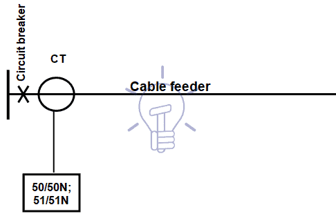
Figure 1 – Overcurrent protection wiring diagram
Let us consider the situation of a cable feeder between stations A and B, being B located downstream of A.
The overcurrent protection at the supply end of the feeder at station A must operate for all faults on the feeder, but should not operate for faults beyond station B.
If we first consider an instantaneous overcurrent relay, then setting is determined by the magnitude of the fault current at the end of the feeder at station B that is the lower fault current on the cable.
Ideally the relay will be set for that fault current and it should not operate for any fault beyond station B.
However, in practice it is not possible to be so precise for the following reasons:
- It is not possible for the relay to differentiate between faults which are very close to, but which is on each side the Bus ‘B’, since the difference in the currents would be extremely small.
- Inaccuracies in CT and relays, and the effects of distortion of the current waveform under transient conditions produce errors in the response of the protection scheme.
- The magnitude of the fault current cannot be accurately established since all of the parameters may not be known, and the source impedance of the power system changes as generators are put in and out of service.
One solution to solve this problem is to set the instantaneous overcurrent relay to overreach the remote terminal and introduce a definite time delay in tripping the circuit breaker.
This time delay will allow the overcurrent relays at the remote station to operate to clear faults beyond bus B before the time delayed tripping can take place at the supply station A.
This type of time delay has the major disadvantage that all faults will be slow cleared even very close-in faults, which have the highest magnitude of fault current.
- Related article: Design and Installation of EHV/EHV and EHV/HV Substations
This time-delayed clearing of high fault currents is usually unacceptable, and the most common feeder protection scheme, which overcomes the problem, utilizes an inverse time overcurrent relay (51) in conjunction with the instantaneous overcurrent relay (50).
In order to ensure that the instantaneous overcurrent relay will not unnecessarily operate for faults at the remote station, (which should be cleared by the overcurrent protection or fuses at that station) then it must be set to protect only part of the feeder. A safe maximum for most types of relay is 80% of the feeder length.
The limit is determined by the characteristics of the relay used, and the length of the feeder. If the feeder is long a high percentage of the line can be protected; but with short lines it may be less; and with very short lines it may not be possible to apply instantaneous overcurrent protection.
This type of protection is known as High-Set Instantaneous (HS) overcurrent protection.
With such a relay set to detect faults on 80% of the feeder, the remaining 20% is left unprotected. This is, of course, not acceptable. To provide protection for the last 20% of the feeder a time-graded, or inverse definite minimum time relay can be used.
The inverse definite minimum time” relay has a characteristic “time-current” curve as shown in Figure 2.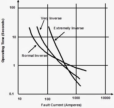
Figure 2 – Characteristic “time-current” curve of inverse definite minimum time relay
Using this characteristic “time-curve” it shall be defined the co-ordination of upstream and downstream protections, a topic that was discussed at Section 3.3.
Now let us look at a typical utility feeder which supplies customer transformers at many different points along its length.
The same High-Set Instantaneous Overcurrent and Inverse Timed Overcurrent relays are used, and the HS relay must be set such that it does not operate for faults beyond the first tap.
HS relay will therefore be set to operate for faults up to 80% of the distance to the first tap.
The criteria used for setting the Inverse-Timed Overcurrent relay are:
- The relay must not operate for the maximum load current that will be carried by the feeder.
- The relay setting must be sensitive enough for the relay to operate and clear faults at the very end of the feeder.
- The relay operating characteristic must be set to coordinate with other protection devices, such as fuses, ‘downstream’ from the supply station.
This type of protection scheme will provide adequate protection for feeders.
However, there are some disadvantages with this arrangement, particularly on long overhead feeders. The main disadvantage is that most faults will be slow in clearing because the inverse time overcurrent relay must operate. This slow fault clearing is usually disturbing to customers on the affected feeder.
Related Article: Power Transformers Maintenance, Diagnostic & Monitoring
The criteria used for setting the High-set Instantaneous Overcurrent Relay are:
- The relay must be set to operate for faults up to, but not beyond, the first tap from the feeder.
- In practice, the relay is set to operate for faults up to 80% of the distance to the first tap.
- This provides high-speed clearance for the high level faults close to the supply
In networks with a ringed type configuration fault current can flow in either direction, and the feeder overcurrent protection at the supply station may require directional supervision on those feeders that in normal situation have only one current direction.
A directional relay – directional phase overcurrent (67) and directional earth overcurrent (67N) – must be used when the phase-to-earth short-circuit current (I”K1) is lower than the maximum residual capacitive current (See note below) (ICM). in the same situation – ICM ≥ I”K1.
Phase-to-earth short-circuit current depends on the neutral grounding system of the network.
Directional overcurrent protection comprises overcurrent relay and power directional relay.
The power directional relay is not used to measure power, but is arranged to respond to the direction of power flow.
The protection relay is connected to CT and VT, as shown in Figure 3.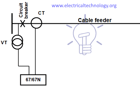
Figure 3 – Directional overcurrent protection wiring diagram
![]()
Related Posts:
- Power Transformer Protection & Faults
- Power Transformers Maintenance, Diagnostic & Monitoring
- Transformers Fire Protection System – Causes, Types & Requirements
- Motor Protection – Types of Faults and Protection Devices
- Generator Protection – Types of Faults & Protection Devices
- HV And MV Switch Disconnectors And Isolators in Power System
- How To Locate Faults In Cables? Cable Faults, Types & Causes
- Fault Current Limiter and Their Types
- All About Electrical Protection Systems, Devices And Units
- GFCI: Ground Fault Circuit Interrupter. Types, Working & Applications