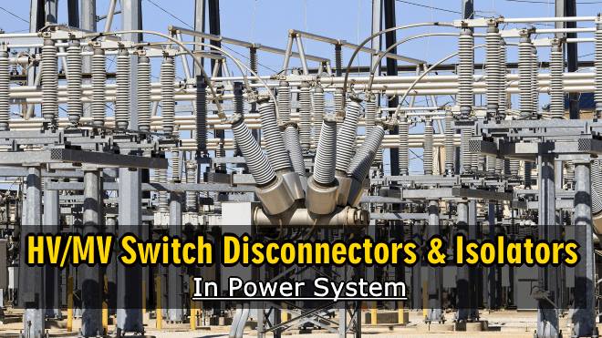
HV And MV Switch Disconnectors And Isolators in Power System
HV/MV Switch Disconnectors And Isolators in Substation & Overhead Lines
Introduction HV/MV Switch Disconnectors And Isolators
High Voltage (HV) and Medium Voltage (MV)[1] installations require equipments to switching and/or isolating circuits or parts of circuits.
For that purpose switch-disconnectors and isolators are used. These equipments must comply with the following IEC[2] Standards:
- 60038 – IEC standard voltages
- 61936-1 – Power installations exceeding 1 kV a.c. – Common rules
- 62271 – Standards for high-voltage switchgear and control gear
Related Post: Difference between Circuit Breaker and Isolator / Disconnector
Switch Disconnectors
Switching operations can be performed through switch-disconnectors, equipments that are able to be operated on-load and can withstand and extinguish electric arc that is produced when the rated current of the installation is interrupted.
Switch-disconnectors are nowadays used only in MV installations, most commonly in MV switchgears and in MV overhead lines (see Figure 1) and they have usually an arcing chamber (air or SF6 insulated) to extinguish the arc, but they also perform that extinction in the air (Air Break Switch – ABS).
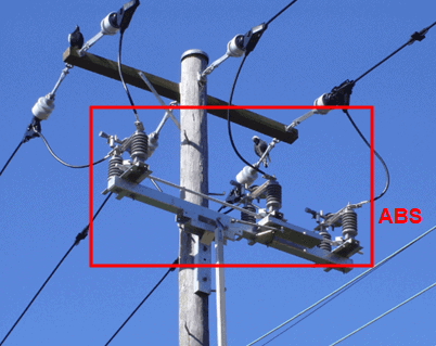
Figure 1 – Disconnecting-switch in overhead line
Characteristics of Switch Disconnectors
Main characteristics of switch-disconnectors are:
- Rated voltage: 2 kV; 12 kV; 17.5 kV; 24 kV; 36 kV
- Rated current: 400 A; 630 A; 1,250 A
- Rated short-time withstand current (3 s): 5 kA; 16 kA; 20 kA; 25 kA
Switch-disconnectors may be mechanical (lever or crank) or motor operated (local or remote) and provided with earthing switches, mechanically interlocked, and release coils; some utilities used them associated with fuses for the protection of MV/LV[3] distribution power transformers (usually with rated power up to 630 kVA), as represented in Figure 2.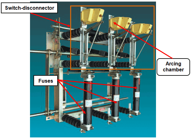
Figure 2 – Switch-disconnector associated with fuses
In these situations fuses must be equipped with acting strikers to mechanically open the switch-disconnector, to avoid the functioning of installation with only two phases; the switch-disconnector must have a tripping coil to allow the transformer protections to actuate.
Isolators
Isolators, also known as disconnectors, are used in HV and MV installations to isolate a circuit or parts of a circuit and to ensure, for safety reasons, to the operators and maintenance teams a visible interruption of the circuit.
Similar to MV switch-disconnectors, MV isolators are installed in MV switchgears and in MV overhead lines. HV isolators are generally installed outdoors, in AIS substations (Air Insulated Substation), seated in metallic structures, or indoors, in GIS substations (Gas Insulated Substation).
Isolators are not able to be withstand and to extinguish electric arc and they can only be operated off-load. If an isolator is operated on load an arc blast and an explosion can occur and provoke damages to persons and equipments.
Characteristics of Isolators
Main characteristics of isolators are:
- Rated voltage
- MV: 2 kV; 12 kV; 17.5 kV; 24 kV; 36 kV
- HV: 5 kV; 123 kV; 170 kV; 245 kV, 300 kV; 420 kV; 550 kV; 800 kV
- Rated current
- MV: 400 A; 630 A; 1,250 A
- HV: 2,000 A; 2,500 A; 3,150 A; 4,000 A; 5,000 A
- Rated short-time withstand current (3 s)
- MV: 5 kA; 16 kA; 20 kA; 25 kA
- HV: 50 kA; 63 kA; 80 kA
Isolators may be mechanical or motor operated (local or remote) and may provided with earthing contacts, mechanically interlocked with main contacts. Usually earthing contacts are only mechanical operated. HV isolators may be single pole or three poles operated.
Motor is controlled by one closing coil and one opening coil, electrically interlocked. Limit switches are used to stop the motor when the isolator reaches its final position – open or closed.
Local mechanical operation of isolators is usually an appellate maneuver, using a crank, which must suppress electrical control.
Mechanical and/or electrical interlocking must be provided to avoid on-load operations.
Types of HV Isolators
HV isolators are basically of three types:
- Two-columns centre or double rotating (horizontal – Figure 3 – or vertical – Figure 4)
- Pantograph (single-column) – Figure 5
- Earthing isolators – Figure 6
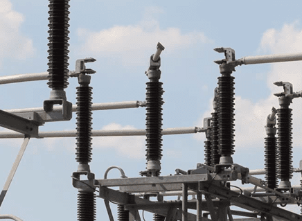 Figure 3 – Centre horizontal rotating isolator
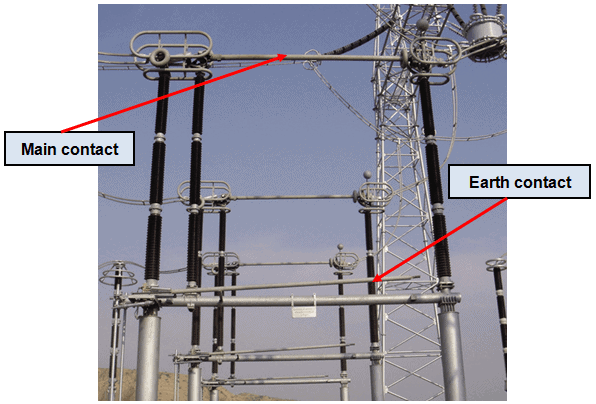 Figure 4 – Double vertical rotating isolator
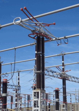 Figure 5 – Pantograph isolator
Pantograph isolators allow the connection of conductors at different levels and have the possibility to be decoupled for testing when the busbar is in operation.
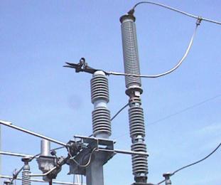 Figure 6 – Earthing isolator
Earthing isolators are mostly used for busbar grounding.
- You may also read: Design of Grounding / Earthing System in a Substation Grid
During isolators testing is a good practice to place main contacts in a position between “opened” and “closed”, to avoid mechanical damages in the equipment if the connections of the motor are swapped over.
![]()
You may also read:
- Corona Effect in Transmission Lines in Power System
- SCADA Systems for Electrical Distribution
- What Exactly Is A Smart Grid? Smart Grid Applications