Types of Active Low Pass Filters
Different Types of Active Low Pass Filters & Configuration
Active Filter
The active filter is a type of filter that comprises of one or more than one active component such as transistors, amplifiers or OP-Amps. In contrast to passive filters, Active filter’s have an amplification factor which can be modified. They have high input impedance and low output impedance which nullifies the loading effect that occurs in passive filters.
Low Pass Filter
Low pass filter or LPF is a type of filter that allows signals having frequency lower than a specific frequency known as cut-off frequency & blocks higher frequency signals.
Low pass filters are of two types
We will only discuss the active low pass filter in this article as we have already explained about passive low pass filters in separate article. Active low pass filters are classified according to the order of the filter. We will discuss 1st & 2nd order active low pass filters.
- Related Post: Filters, Types of Filters and Their Applications
First Order Active Low Pass Filter
First order Active low pass filter is a simple filter that is made of only one reactive component i.e Capacitor along with an active component Op-Amp. A resistor is used with the Capacitor or Inductor to form RC or RL low pass filter respectively. RC active low pass filters using op-amps are briefly discussed in this article.
The roll off rate of first order low pass filter is -20dB/decade or –6dB/octave. The roll-off rate depends on the order of the filter.
Roll-Off Rate = -20n dB/decade = -6n dB/octave
Where n = order of the filter
One should already know the basic configuration of an op-amp before its implementation. Op-Amp can be used in the following configurations:
- Non-Inverting (voltage follower) Configuration
- Buffer (Unity gain)
- Inverting Configuration
Related Post: Types of Passive High Pass Filters
Non-Inverting or Voltage Follower Configuration:
As you know that in the voltage follower configuration, the input signal is applied at the positive terminal of the Op-Amp. the output voltage is in phase with the input voltage that is why it is called voltage follower. But to achieve the desired result (of low pass filter), the schematic can be designed in a variety of configurations.
We will discuss two such configurations each with some benefits over the other.
Standard Op-Amp Configuration:
The standard configuration implies the use of Op-amp as a separate amplifier at the output of a traditional RC Low Pass filter circuit. It can be realized from the schematics given below.
The gain of this voltage follower amplifier is given by :
Gain = A = 1+ (R2/R1)
We can use it with or without amplification depending on the requirement of the filter.
- Related Post:Types of Active High Pass Filter
Unity Gain or Buffer Configuration
In such configuration, the gain of the Op-Amp remains unity (one) i.e. the output signal amplitude is equal to the input signal amplitude. There is no feedback resistor, so the gain of the Op-Amp (Amplifier) becomes 1.
The schematic for voltage follower unity gain low pass filter is given below.
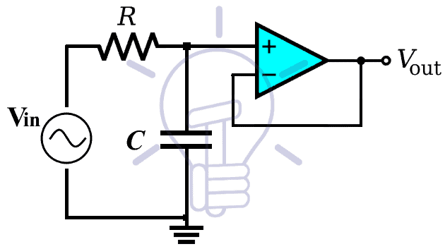
The fact that this is a voltage follower configuration, the output signal will be the exact same replica of the input signal.
Example:
Let’s simulate an example of this schematic using Proteus to evaluate the frequency response of this circuit.
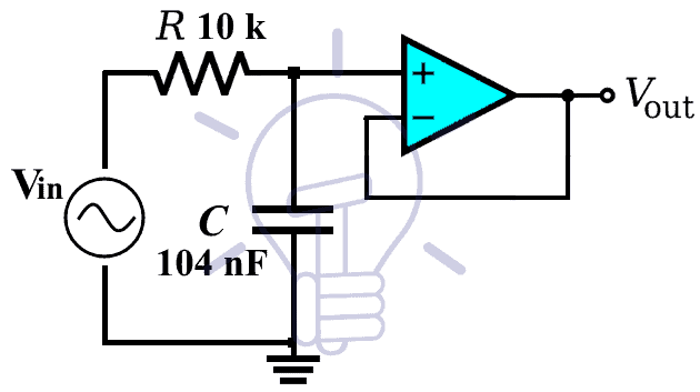
The resistor used in this example of 10 KΩ & the capacitor is 104 nF.
So, the cutoff frequency of this filter will be:
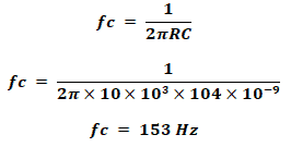
Here is the simulated graph using Proteus which clearly shows the corner frequency (cutoff frequency) which actually lies at -3dB.
The question here is “why we use an Op-Amp amplifier when there is no amplification?”. The answer is, to provide high input and low output impedance. By using unity gain op-amp between the stages of multistage amplifiers, it ensures the maximum signal transfer to the succeeding stage.
- Related Post: Types of Diodes and Their Applications
Non-Inverting Filter With Amplification:
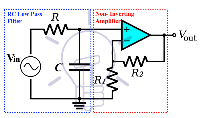
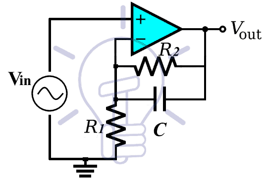
This type of filter uses the Op-Amp as a voltage amplifier. The amplification aspect of this configuration provides a voltage gain for any weaker input signal. The schematic of a non-inverting RC low pass filter is given below;
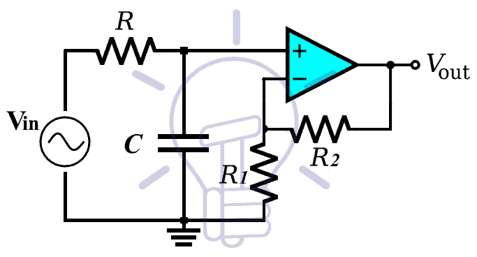
The first part of the circuit i.e. Resistor R & capacitor C forms the traditional RC low pass filter which has the same properties, as discussed in the passive RC low pass filters. The second part of the schematic given above is the Op-Amp which provides the voltage gain.
The Voltage Gain:
The feedback resistor R2 & R1 are responsible for the gain of the amplifier. The equation used for the voltage gain of the non-inverting amplifier is;
Gain = Av = 1+ (R2/R1)
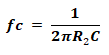
Cutoff Frequency;
The cutoff frequency, also known as -3dB frequency, is determined by the RC filter connected to the input of the Op-amp. The -3dB frequency is given by;

- Related Post: Types of Rectifiers and Their Operation
Gain at Cutoff Frequency:
In passive filters, the gain at cutoff frequency is considered at -3dB. That is because the passive filters have unity gain i.e. 0dB. So the cutoff frequency point is given by 0dB – 3dB = -3dB
Whereas, the active filter gain at corner frequency will be -3dB of the gain of the filter.
the gain of the active filter in decibels is;
Gain Av in dB = 20 log(Av)
Suppose the active filter gain is 10dB. So the gain at the cutoff frequency of that filter would be;
Gain at fc = 10dB – 3dB = 7dB
The system will allow any frequency below this cutoff point and blocks any higher frequencies.
So the bandwidth of the system become fc Hz.
- Related Post: Counter and Types of Electronic Counters
Example:
We are going to use Proteus for the simulation of this circuit and its frequency response.
The resistors used in this examples are R = 10 kΩ, R1 = 1 kΩ & R2 = 9 KΩ
& the capacitor C = 104 nF.
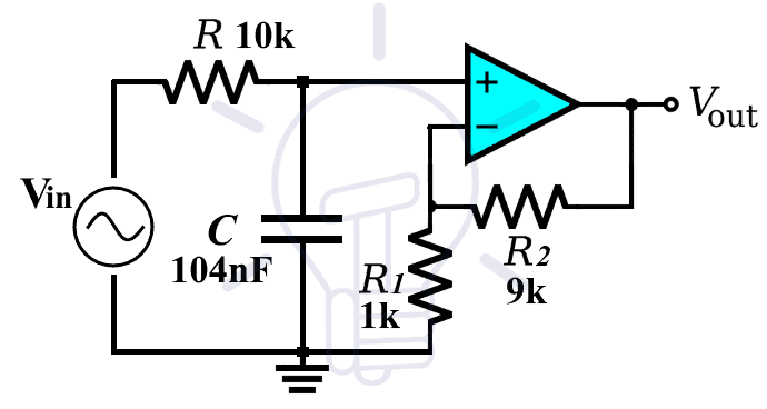
So the cut off frequency of the filter is ;
the gain of the filter is;
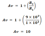
The gain in dB;
Av = 20 log(10)
Av = 20 dB
So the gain at cutoff frequency is;
Gain at fc = 20dB – 3dB = 17dB
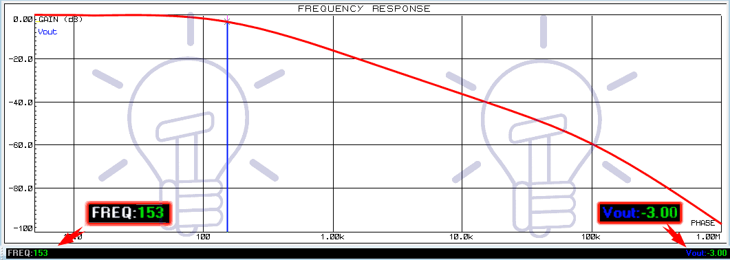
To confirm our calculations, we are going to simulate this circuit on Proteus & evaluate its frequency response.
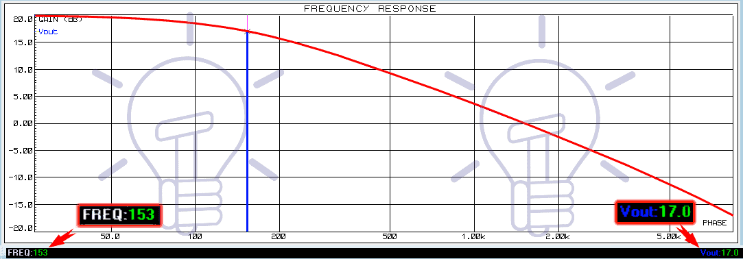
From the frequency response given above, you can see the cutoff frequency is 153 Hz at gain 17 dB.
The bandwidth of this filter is 153 Hz.
- Related Post: Types of Digital Latches – SR D Latches
Limitation:
This design does have one flaw. The output impedance does not change but the input impedance may vary because of the source impedance. It may either decrease or increase, which would impact on the characteristics of the filter response.
Improved Design
To improve the design of the filter discussed above, the capacitor position is changed from the input side of the circuit to the parallel connection with the feedback resistor. This way the input source impedance won’t affect the impedance of the filter. The circuit for non-inverting low pass filter is given below:
The cutoff frequency of this filter is calculated by the equation:
The gain of the filter is the same as the previous design i.e.
Gain = Av = 1+ (R2/R1)
And the gain at the cutoff frequency calculated by subtracting 3dB from the gain of the filter in dB.
Example:
Let’s simulate a circuit with the same value of capacitor and resistor using Proteus software.
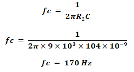
The resistor R2 = 9 kΩ & R1 = 1 kΩ & the capacitor C = 104 nF.
Using the equation of the cutoff frequency, we calculate;
Where the gain of the filter is;
Converting the gain of the filter into decibels;
Av = 20 log(10)
Av = 20 dB
So the gain at cutoff frequency is;
Gain at fc = 20dB – 3dB = 17dB
The cutoff frequency point 170 Hz lies at the gain of 17 db. We can confirm it by observing the frequency response of the circuit using Proteus.
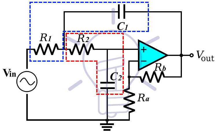
Inverting Amplifier Low Pass filter:
This type of filter is made using the Operation amplifier in inverting configuration. In inverting configuration, the input signal is applied to the negative terminal of the Op-Amp & the positive terminal is grounded. The output of this filter is inverted, other than that the frequency response is the same as the non-inverting filter.
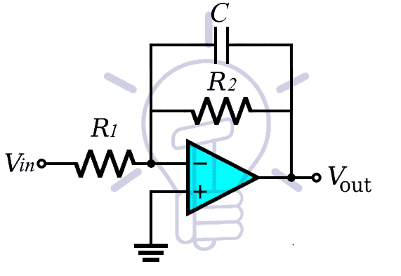
The schematic of the inverting amplifier low pass filter shows the input signal applied to the negative terminal of the Op-Amp.
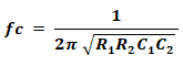
The equation for the cutoff frequency of this filter is;
Also, the gain of the system is calculated using the equation;
Av = – (R2/R1)
The negative sign shows that the output is inverted.
It is a first order filter, which means the roll-off rate in the frequency response is -20dB/decade or -6dB/octave.
Following is an example of an inverting amplifier low pass circuit.
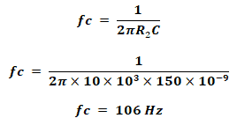
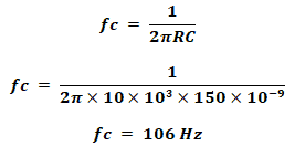
Let suppose the resistor R1 = 1 kΩ, R2 = 10 kΩ & Capacitor C = 150 nF
The cutoff frequency of the filter is;
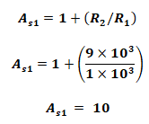
The gain of the Filter is;
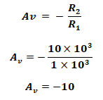
The gain of this filter is 10. The negative sign implies the output is inverted.
Converting the gain into dB;
Av = 20 log(10)
Av = 20 dB
So the gain at cutoff frequency is;
Gain at fc = 20dB – 3dB = 17dB
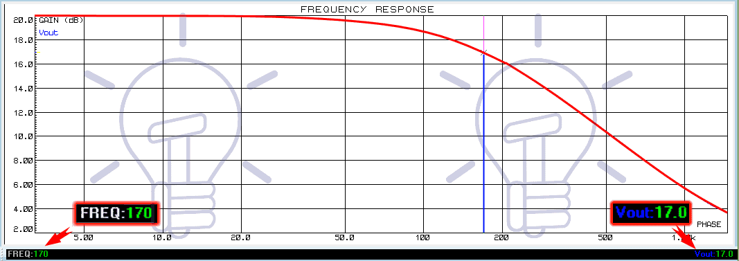
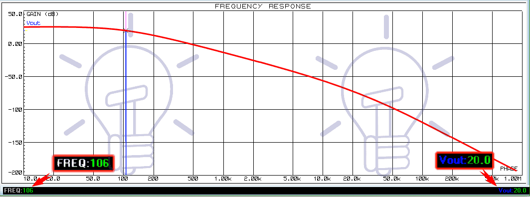
The frequency response graph of the given example is simulated using Proteus. The graph clearly shows the 17dB gain point at which the corner frequency is 106 Hz.
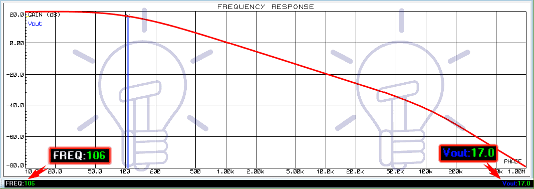
The cutoff frequency is given at the bottom left corner & the gain is given at the bottom right corner for the selected point. The frequency blocks any higher frequencies from this point.
- Related Post: Types Of Capacitors | Fixed, Variable, Polar & Non-Polar
Second Order Active Low Pass Filter:
The second order active low pass filter are very commonly used in many applications.
A second order filter has 40 dB/decade roll off or 12dB/octave roll off. Whereas the first order filter has 20 dB/decade or 6dB/octave.
To get a second order filter a simple method is to cascade two first-order filters. Other designs of the 2nd order filters are named after their inventor such as Sallen-Key filter, Butterworth filter, Chebyshev filter & Bessel, etc.
By Cascading:
Cascading two first order filters together provide a 2nd order filter. The schematic of cascading a two 1st order filter is given below:
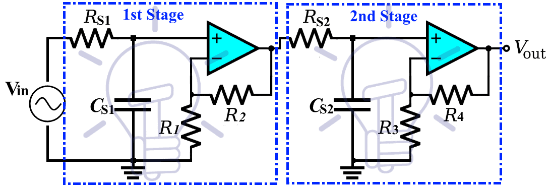
This schematic shows a non-inverting filter cascaded together. Cascading two inverting filters will also form a 2nd order filter with the same characteristics as this filter.
Gain Of Filter
The gain of the second order filter is a product of gain of both stages i.e.
Gain, Av = As1 x As2
As1 = 1 + (R2/R1)
As2 = 1 + (R4/R3)
If the gain of both stages is given in dB, then the total gain is calculated by summation of both gains.
Av (in dB) = As1 + As2
Cutoff Frequency:
The equation for cutoff frequency is;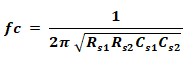
if the resistor Rs1 = Rs2 = R & capacitor Cs1 = Cs2 = C then the equation becomes;
The Gain at Cutoff Frequency;
As we know that the gain at the cutoff frequency for the first stage of the filter is at -3db. Same as the case with second stage filter. When you combine them together, the gain at the cutoff frequency for the overall filters lies at -6db. We will confirm that in an example.
Example:
Let’s suppose the Rs1 = Rs2 = 10 kΩ & capacitor Cs1 = Cs2 = 150 nF , and the gain resistors R1 = 1KΩ, R2 = 9KΩ, R3 = 1KΩ, R4 = 1KΩ.
Since the RC network resistors and capacitors have the same values, the cutoff frequency becomes;
The gain of the first stage amplifier is;
The gain of the second stage is;

The total gain of the filter;
Av = 10 x 2
Av = 20;
The total gain in dB;
Av = 20 log(20)
Av ≈ 26 dB
So the gain at the cutoff frequency is;
Gain at fc = 26 dB – 6 dB = 20dB.
We can confirm the result from the simulated frequency response graph using Proteus.
Sallen-Key Low Pass Filter:
Sallen-Key topology filters provide a variety of 2nd order frequency selective filters including low pass, high pass, band pass & band reject filter.
It is a form of voltage controlled voltage source (VSVS) which uses a single op Amp with two capacitor & two resistors. And off-course the two other resistors for the gain of the filter.
There are two RC filter networks i.e. R1C1 & R2C2. These two filters set the characteristics of the filter frequency response.
The cutoff frequency of this filter is;
If the resistor R1 = R2 = R & Capacitor C1 = C2 = C, the equation of cutoff frequency becomes;
The gain of the filter is given by;
A = 1 + (Rb/Ra)
- Related Post: Different Types of Sensors with Applications
Quality Factor Q:
The quality factor Q determines the behavior of the frequency response of the system i.e. under damp, overdamp or critically damp systems. These systems are discussed down below;
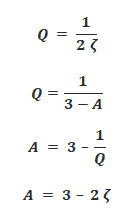
Whereas the equation for the quality factor Q of a Sallen-Key Low Pass filter is;
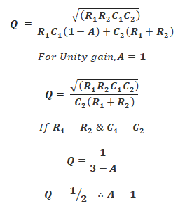
The frequency response of a Sallen-Key filter varies with gain A, Quality factor Q & the damping factor ζ (zeta). The Q factor & damping factor ζ are inversely proportional to each other
It shows that the Q factor depends on the gain of the filter (considering the resistor & capacitor are the same). So the gain A for a non-inverting amplifier should be between 3 & 1. The damping factor ζ should be between 0 & 2.
Remember, These conditions only apply when the resistor R1 = R2 and capacitors C1 = C2.
Systems Based on Q Factor:
- If Q < ½, the system is called Over Damped. The system has a low-quality factor. it does not oscillate at any frequency. A low-quality filter acts as a 1st order low pass filter.
- If Q = ½, the system is called Critically Damped. It does not oscillate at any frequency just like an over damped filter. But it has 40db/decade or 12db/octave roll-off rate with its cutoff frequency at -6db gain because of the steeper roll-off rate. it is a perfect case for 2nd order filter.
- If Q > ½, the system is called Under Damped having a high-quality factor. Such a system oscillates at a frequency near the cutoff frequency known as peak frequency. There is a huge gain at peak frequency because of the system oscillation.
Frequency Response
Frequency response graph for each of the above-mentioned condition is given below.
Under damped condition with fc = 106 Hz, A = 2.98 = 9.48 db, Q = 50.
The value of the components are, Resistor R1 = R2 = 10 KΩ, capacitor C1 = C2 = 150 nF. Ra = 10 KΩ, Rb = 19.8 KΩ
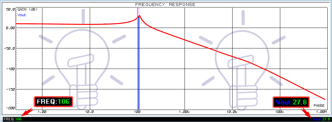
The response shows the system is oscillating at the near cutoff frequency with a huge gain.
Critically damped condition with fc = 106 Hz, A = 1 = 0db, Q = 1/2.
The value of the components are, Resistor R1 = R2 = 10 KΩ, capacitor C1 = C2 = 150 nF. Ra = 0 Ω, Rb = 0 Ω
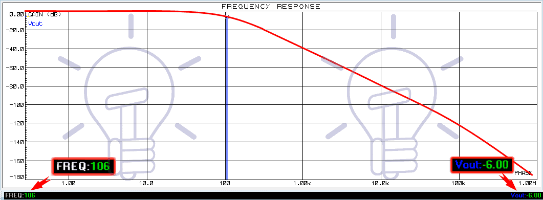
This system response shows a 2nd order filter with 40db/decade or 12db/octave roll-off rate with fc at -6db gain.
Over damped condition with fc = 355 Hz, A = 2 ≈ 6db, Q = 1/10.
The value of the components are, Resistor R1 = 1KΩ, R2 = 10 KΩ, capacitor C1 = C2 = 150 nF. Ra = 10 KΩ, Rb = 10 KΩ
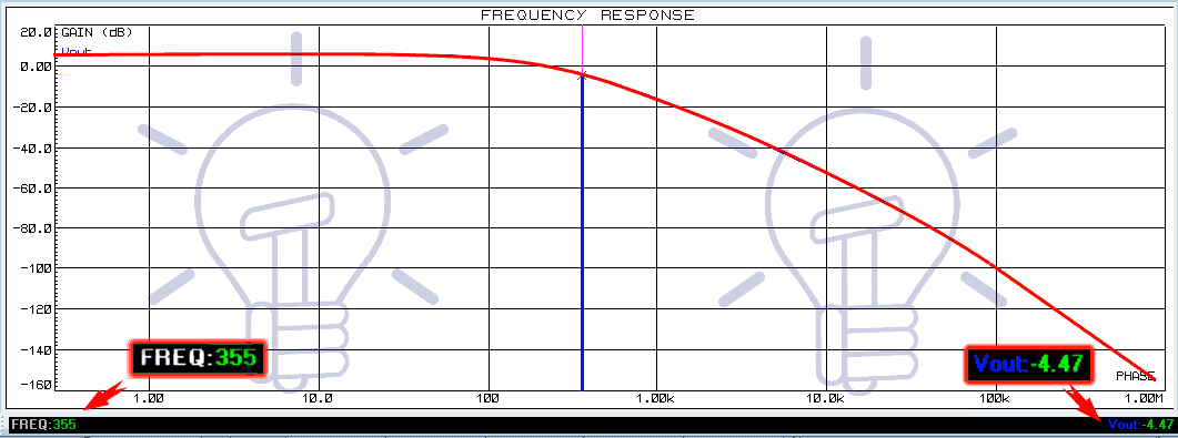
The Overdamped system’s frequency response does not have the steep curve like a 2nd order filter supposed to have. It’s Cutoff frequency fc, which is 355 Hz lies at -4.47 dB instead of 0 dB (A – 6db).
Related Posts:
- Types of Amplitude Modulation (AM) – Advantages & Disadvantages
- Types of Modulation Techniques used in Communication Systems
- Types of Resistive Sensors – Transducer, Potentiometer & Strain Gauge


This article is good for beginners like me in the world electronic electrical engineering, and I hope the readers will get assistance from this electronic article. It’s great that the low-pass gain expression for Butterworth filters can be converted to a high-pass filter by inverting the axis. My input signal is a train of perfect rectangular pulses so maybe the help fo a Butterworth low pass filter could help me with my project so I will consider getting a few filters.