Types of Active High Pass Filter
Active High Pass Filter – 1st Order & 2nd Order Active High Pass Filters
High pass filter is a frequency selecting electronic circuit that controls the frequency components in a signal by attenuating (blocking) the low-frequency components and allowing only high-frequency components.
High pass filters are mainly divided into two types i.e.
- Passive High Pass filter
- Active High Pass filter
An active filter means that its circuit contains an active component such as a transistor, operational amplifier (Op-Amp), etc. for better performance but mainly for amplification.
The benefit of using an active high pass filter is
- It has an amplification factor which increases the amplitude of small signals.
- It has very high input impedance which enables an efficient signal transfer without losing any of it in its preceding circuit.
- The output impedance of active filter is very low, which is perfect for efficient signal transfer to its succeeding stage especially if used in multistage filters.
Related Post: Filters, Types of Filters and Their Applications
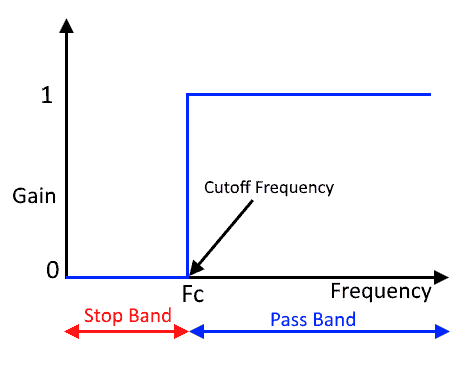
Ideal High Pass Filter:
An ideal high pass filter blocks signal completely having frequency lower than a pre-selected frequency known as cutoff frequency and allow any frequency high than cutoff frequency without any attenuation. The frequency response graph of an ideal filter looks something like this.
Practically, such kind of frequency response is not possible. A real high pass filter does not abruptly block frequency below the cutoff frequency. Instead, the gain slowly decreases with a decrease in the frequency which makes a curve in frequency response. The cutoff point of a practical filter is considered at its half-power i.e. ½ or -3db gain or the point where the amplitude of the output signal is 0.707 times the maximum amplitude. A practical high pass filter has such kind of frequency response.
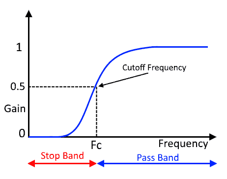
The curve can be made steeper by increasing the order of the filter. It is discussed in this article down below.
- Related Post: Types of Active Low Pass Filters
First Order Active High Pass Filter:
First Order filter is the simplest form of filters that contains only one reactive component i.e. capacitor as we have discussed in the passive high pass filter. In order to convert it into an active filter, an Op-Amp is added to the output of a passive filter.
Now, the Op-amp can be used in different configurations. Each configuration adds in different attributes to the performance of the filter. We will discuss the high pass filter in different configurations.
The main point to note in a first-order filter is its roll-off rate. Roll-off rate is the rate of change in the gain of a filter in its stopband. It shows the steepness in the curve and how fast its gain increases with frequency. First-order filters have a roll-off rate of 20dB/decade or 6db/octave. Roll-off rate of an nth order filter is given by;
Roll Off Rate = -20n dB/decade = -6n dB/octave
Where n = order of the filter
Non-Inverting Configuration:
In a non-inverting configuration, the output signal is in phase with the input signal. The input signal is applied to the non-inverting terminal of the operational amplifier. While its inverting terminal is used for the gain of the amplifier.
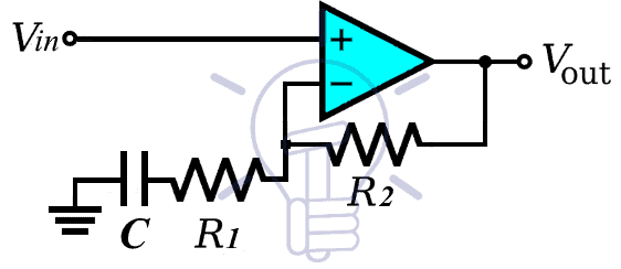
Standard High Pass Filter With Op-Amp
In such kind of configuration, an Op-Amp is connected to the output of a traditional High pass filter which is a simple passive RC circuit described in a passive high pass filter. However, the filter can be designed to use as a unity gain filter also known as a buffer or an amplifier to amplify the amplitude of the signal.
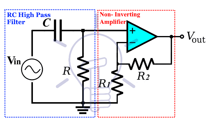
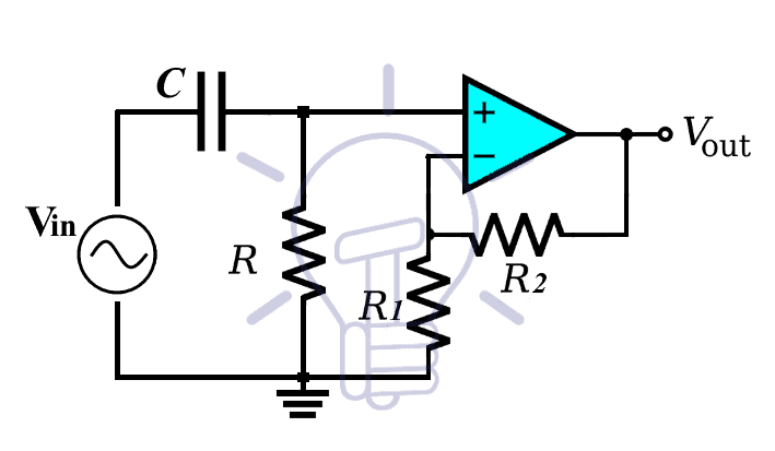
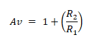
The schematic given above shows a simple RC filter connected with a non-inverting op-amp. The gain of the Op-Amp is given by;
Gain, A = 1+ (R2/R1)
Based on this gain the filter is classified into two types.
- Unity Gain or Voltage Follower Configuration
- Non-inverting Filter with Amplification
Voltage Follower Or Unity Gain Op-Amp Configuration:
In such configuration, the output follows the input which is why it is called voltage follower configuration. There is no amplification because the gain of the op-amp is set as 1 (unity gain). Such configuration of Op-amp is also known as a buffer. Following is the schematic of an active high pass filter with unity gain.
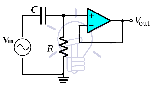
As you can see, there are no feedback resistors so the gain for this particular setup becomes.
A = 1+ (R2/R1)
A = 1
Example:
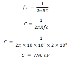
Find the value of the capacitor for a high pass filter having unity gain whose cutoff frequency is at 2KHz. Assume the resistor R is 10 KΩ.
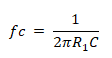
As we know that the cutoff frequency is given by;
Let’s simulate our solution using Proteus tool to verify the cutoff frequency 2 kHz which should be at -3 dB gain.
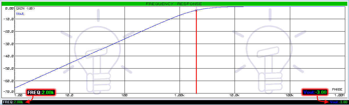
Because the unity gain of the filter (0 dB), it’s cutoff frequency always lies at -3 dB gain. Unity gain Op-Amp or buffer are used between the stages of a multistage amplifier to maintain efficient signal transfer. It is because the Op-Amp increases the input impedance and decreases the output impedance.
Non-Inverting High Pass Filter With Amplification:
In such configuration, the Op-Amp is designed to provide an amplification factor which amplifies the signal. The gain of such amplifier is given by;
Gain, A = 1+ (R2/R1)
The cutoff frequency equation remains the same for this filter. However, the gain at the cutoff frequency is given by subtracting 3 dB from the max gain of the filter i.e.
A-3dB = AdB – 3 dB.
For example, the gain of the filter is 7 dB. The cutoff frequency gain would be 7 – 3 = 4dB.
Example:
Find the value of the resistor and capacitor for a high pass filter? If the gain A of the filter is 5 and the cutoff frequency of the filter is 6.6 KHz.
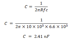
First of all, let’s calculate the value of the resistor and capacitor used for the cutoff frequency R & C.
Assume the value of resistor R= 10 KΩ then the capacitor value is ;
Now, let’s evaluate the value of feedback resistor for gain A = 5. Assume R1 = 1KΩ.
A = 1+ (R2/R1)
R2 = (A – 1) R1
R2 = (5 – 1) 1 KΩ
R2 = 4 KΩ
Now calculate the gain at the cutoff frequency. But first, we need to convert the gain into dB.
AdB = 20 log (A)
AdB = 20 log (5)
AdB = 14.97 dB ≈ 14 dB
Now subtracting 3db
Gain at cutoff frequency,A-3db = AdB – 3dB
A-3db = 14 – 3 = 11 dB
So the gain of the is filter at the cutoff frequency which is 6.6KHz is 11 dB. We are going to simulate this schematic using the Proteus to verify our results. The following schematic & frequency response of this example is following.
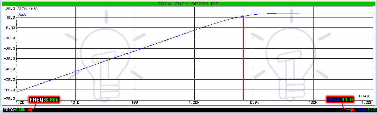
The frequency response shows the cutoff frequency of 6.6 kHz at the gain of 11dB.
- Related Post: Types of Inductors and Their Applications
Limitation of Standard Active High Pass Filter:
Although it is easier to design, there are some limitations in using an operational amplifier at the output end of a passive filter.
- The input impedance of such active filter may vary due to the impedance of the signal source.
- Change in the input impedance of the filter changes the overall performance of the filter.
- The signal from the source circuit does not transfer properly to ensure the maximum gain of the filter & its frequency response.
Improved Design
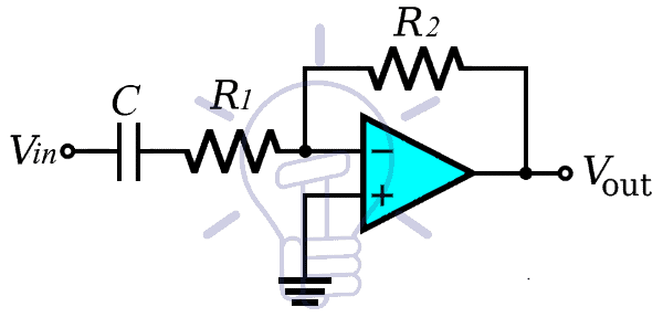
To resolve the problem of loading effect in the filter design above, the capacitor from the input line is removed and connected with the inverting terminal of the operational amplifier as shown in the figure down below. This way the signal source impedance won’t affect the impedance of the filter. The circuit for non-inverting active High pass filter is given below:
The Equation for the cutoff frequency of this filter is calculated by
The gain of the filter is the same as the previous design i.e.
And the gain at the cutoff frequency is calculated by subtracting 3dB from the gain of the filter in dB.
Example:
An Active non-inverting high pass filter having a cutoff frequency of 5KHz with the gain of 10. Find the value of C, R1 & R2 ?
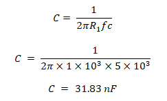
Calculating the value of the capacitor from the cutoff frequency equation:
Assume R1 = 1 KΩ
Now we will calculate the value of the feedback resistor R2, which is given the gain equation of the filter.
A = 1+ (R2/R1)
R2 = (A – 1) R1
R2 = (10 – 1) 1 KΩ
R2 = 9 KΩ
Converting the gain of the filter in decibels;
Av = 20 log(10)
Av = 20 db
So the gain at cutoff frequency is;
Gain at fc = 20db – 3db = 17db
Simulating the given solution of this example will give us a frequency response where we can confirm our results. Here is the frequency response:
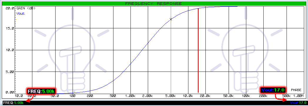
The cutoff frequency of 5KHz at the gain of 17 dB is clearly visible in this graph.
- Related Post: Analysis of a Simple R-L Circuit with AC and DC Supply
Inverting Active High Pass Filter:
To configure the operational amplifier in the inverting configuration, the input signal is applied to the negative (inverting) terminal of the operational amplifier. The non-inverting (positive) terminal of the Op-Amp is grounded. This configuration gives an inverted signal But the frequency response of the filter remains the same.
The schematic of the inverting Active High pass filter shows the input signal applied to the negative terminal of the Op-Amp.
The equation for the cutoff frequency is similar to the non-inverting filter;
Only the gain of the filter change & it’s given by;
Av = – (R2/R1)
The negative sign shows that the output is inverted.
It is a first-order filter, which means the roll-off rate in the frequency response is -20db/decade or -6db/octave.
Example:
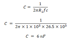
An inverting high pass filter having a cutoff frequency of 26.5 kHz with the gain of 8. Find the value of C, R1 & R2 ?
Assume the value of R1 = 1 KHz
Calculating the feedback resistor R2 value from the equation of the gain of the filter;
A = (R2/R1)
R2 = A R1
R2 = 8 x 1 KΩ
R2 = 8 KΩ
Converting the gain of the filter in decibels;
Adb = 20 log(A)
Adb = 20 log(8)
Av = 18 dB
So the gain at the cutoff frequency is;
Gain at fc = 18db – 3db = 15db
Now we can confirm our calculated values by simulating this example in Proteus. Here is the frequency response for this example.
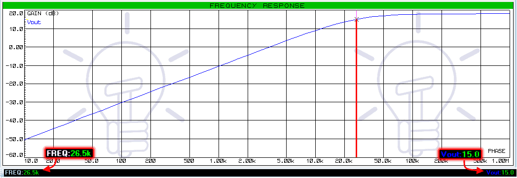
The cursor shows the cutoff frequency of 26.5 kHz at the gain of 15 dB which is calculated cutoff frequency gain.
- Related Post: LVDT: Types of Inductive Sensors
Second-Order Active High Pass Filter:
The second-order filters have two reactive components; in this case, it is capacitors. These second-order filters are preferred over the first order due to its high roll-off rate.
It has the roll-off rate of 40dB/Decade or 12dB/octave providing more steeper gain slope. The first order filter has 20dB/Decade or 6dB/octave.
There are many methods to design a second-order filter. A simple method is to cascade two first-order filters. Other designs for 2nd order filters are named after their inventor such as Sallen-key, Butterworth, Chebyshev & Bessel filters, etc.
Cascading Method:
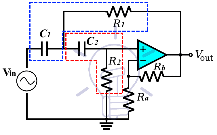
To design a 2nd order active high pass filter, two 1st order active high pass filters are cascaded together as shown in the figure down below;
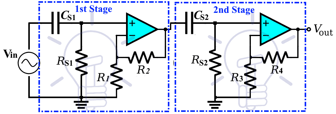
This design shows two stages of non-inverting filters cascaded together. Two inverting filters can also be cascaded together to form a 2nd order filter with the same features.
- Related Post: Types of Rectifiers and Their Operation
Gain of Filter
The gain of a second-order cascaded filter is a product of gain of its both stages i.e.
Gain Av = As1 x As2
As1 = 1 + (R2/R1)
As2 = 1 + (R4/R3)
If the gain of both stages is given in dB, then the total gain is given by the summation of both gains.
Cutoff Frequency:
The cutoff frequency of the cascaded filter is
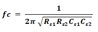
if the resistor Rs1 = Rs2 = R & capacitor Cs1 = Cs2 = C then the equation becomes;
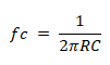
The Gain at Cutoff Frequency;
The cutoff frequency gain of 2nd order cascade filter is at -6db. It is because each stage provides -3db gain at the cutoff frequency. Thus the overall gain at cutoff frequency becomes -6db. We will confirm this in the coming examples.
- Related Post:Types of SSR Relays – Construction & Operation
Example:
Cascade Active high pass filter having resistors Rs1 = Rs2 = 2.2 kΩ & capacitor Cs1 = Cs2 = 100 nF , and the gain resistors R1 = 1KΩ, R2 = 4KΩ, R3 = 1KΩ, R4 = 9KΩ. Find the cutoff frequency fc & gain of the filter Av.
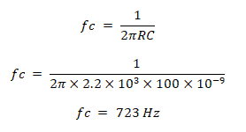
Since the RC network resistors and capacitors have the same values, the cutoff frequency becomes;
Now to calculate the gain of the overall filter, we will calculate the gain of each stage. The gain of the first stage filter is

The gain of the second stage is;
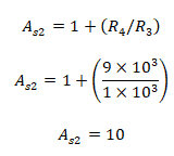
The total gain of the filter;
Av = 5 x 10
Av = 50;
The total gain in dB;
Av = 20 log(50)
Av ≈ 34 dB
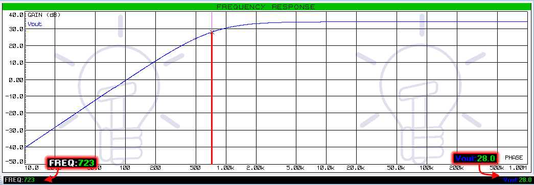
So the gain at the cutoff frequency is;
Gain at fc = 34 – 6 = 28 dB.
Here is the frequency response of this example from simulation using Proteus.
- Related Post: Types of Diodes and Their Applications
Sallen-Key High Pass Filter:
Sallen-Key topology is used for a variety of 2nd order frequency-selective filters including low pass, high pass, bandpass & band-reject filter.
It is a form of voltage-controlled voltage source (VSVS) which uses a single op Amp with two capacitor & two resistors. Also, the two feedback resistors used for the gain of the filter.
There are two RC filter networks i.e. C1R1 & C2R2. These two filters set the characteristics of the overall 2nd order filter’s frequency response.
The cutoff frequency of this filter is;
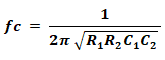
If the resistor R1 = R2 = R & Capacitor C1 = C2 = C, the equation of cutoff frequency becomes;
The gain of the filter is given by;
A = 1 + (Rb/Ra)
But the frequency response of the Sallen-Key filter varies with gain A, Quality factor Q & the damping factor ζ (zeta).
The quality factor Q for this filter is given by
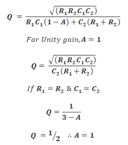
The Q factor & damping factor ζ (zeta) are inversely proportional to each other;
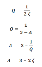
As you can see, the Q factor is related to the gain of the filter. So the gain A for a non-inverting amplifier should be between 3 & 1. The damping factor ζ should be between 0 & 2. Remember, these conditions only apply when both resistors and capacitors are equal in values.
- Related Post: Counter and Types of Electronic Counters
The Q factor determines the system & its frequency response whether it will oscillate or not.
- If Q < ½, the system is called overdamped. It has a low Quality factor Q. The system does not oscillate at any frequency. A low-quality filter acts as a 1st order High pass filter.
- If Q = ½, the system is called critically damped. It does not oscillate at any frequency just like an overdamped filter. it has 40db/decade or 12db/octave roll-off with its cutoff frequency at -6db gain because of the steeper roll-off rate.
- If Q > ½, the system is called underdamped having a high Quality factor Q. Such a system oscillates at a frequency near cutoff frequency.
Frequency response graph for each condition is given below;
- Under damped condition with fc = 5 KHz, A = 2.98 = 9.48db, Q = 50.
Using the equation given above, The calculated values of the components are, Resistor R1 = R2 = 10 KΩ, capacitor C1 = C2 = 10.6 nF. Ra = 10 KΩ, Rb = 19.8 KΩ
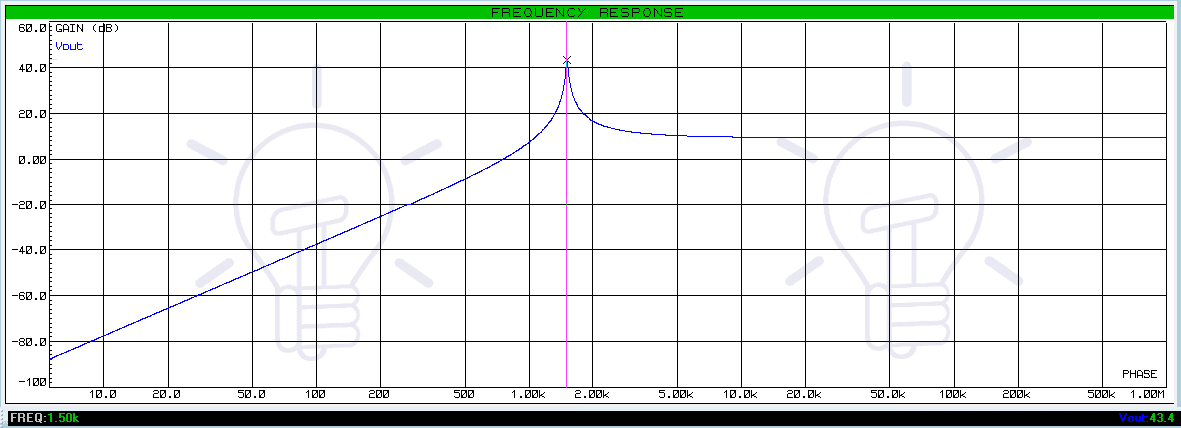
Its frequency response shows the system is oscillating at the cutoff frequency with a huge gain.
- Critically damped condition with fc = 1.5 KHz, A = 1 = 0db, Q = 1/2.
Calculating the values of the components from the equation given above we got, Resistor R1 = R2 = 10 KΩ, capacitor C1 = C2 = 10.6 nF. Ra = 0 Ω, Rb = 0 Ω
This system response shows a 2nd order filter with 40db/decade or 12db/octave roll off rate with fc at -6db gain
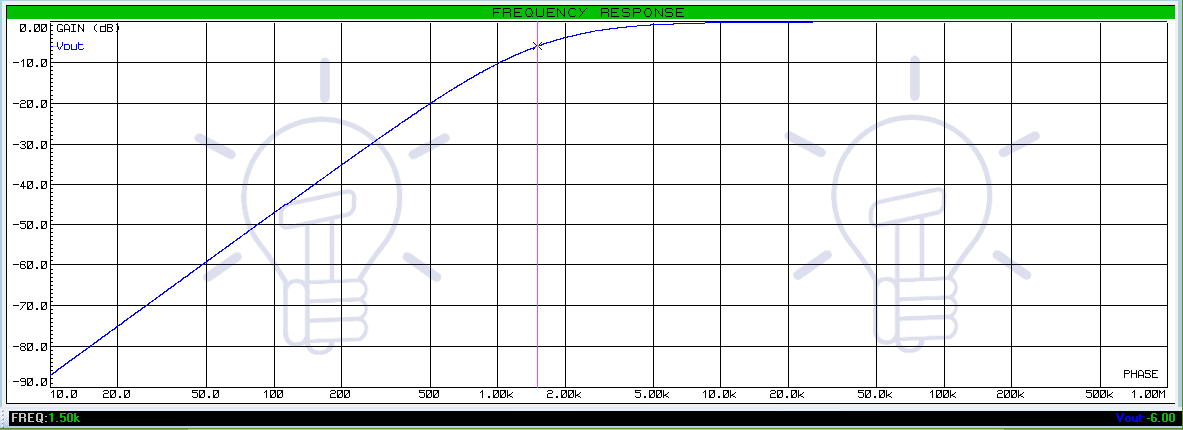
- Over damped condition with fc = 1.5 KHz, A = 2 ≈ 6db, Q = 1/10.
The value of the components are, Resistor R1 = 1KΩ, R2 = 10 KΩ, capacitor C1 = C2 = 33.5 nF. Ra = 10 KΩ, Rb = 10 KΩ

The frequency response curve of such overdamped filters does not have steeper curves like a 2nd order filter. The cutoff frequency, which is 1.5KHz lies at the gain of -2dB instead of 0 dB (A – 6db).
Related Posts:


