Types of Passive High Pass Filters
Types of Active High Pass FilterTypes of Passive High Pass Filters – 1st Order & 2nd Order Passive Filters
High Pass Filter:
Such type of frequency filters that blocks or attenuate any low-frequency signal & allow only high-frequency signals. It blocks frequency less than a selected frequency known as corner or cutoff frequency.
There are two main types of high pass filter;
We will focus on passive High pass filter in this article & discuss it in detail with examples. The passive high pass filters will be discussed in next post.
Passive High Pass Filter:
A Filter that is made up of only passive components such as resistor, capacitor & inductor is called Passive filter. Passive filters do not need any external source thus they have no gain i.e. the output signal amplitude is always equal to or less than the input signal amplitude.
The design of a passive filter is very simple & the components used are very cheap.
A simple High Pass filter is designed using a resistor with a capacitor (known as RC circuit) & with Inductor (known as RL Circuit). In this article, we will discuss both RC & RL high pass filters with examples.
- Related Post: Types of Active Low Pass Filters
Types of Passive High Pass Filters
First Order Passive High Pass Filter:
First order filters contain only one reactive component i.e. either capacitor or inductor. It is the simplest form of filter made from only two components with resister being common in both designs i.e. RC & RL.
Frequency Response & Terms Used in it:
In order to understand a filter, you need to study its frequency response. Frequency response or bode plot is a graph of a circuit which shows its gain on the vertical axis with respect to the frequency on the horizontal axis.
However, the frequency response contains some key terms which need to be discussed to fully understand it. Here is a frequency response of First-order High Pass filter.
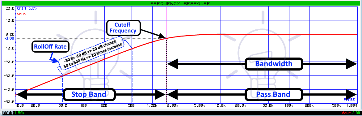
This frequency response clearly shows the gain of a high pass filter which is increasing with the frequency.
Cutoff Frequency or Corner Frequency:
The frequency at which the gain of the filter is ½ or -3db or the output amplitude is 70.7% (1/√2) of the input is known as corner frequency it is denoted by fc. It is the boundary between passband & stop band of a filter.
Stop Band:
The Stop band is the band of frequencies that is blocked by the filter. in a high pass filter, the frequency that is lower than the cutoff frequency fc is the stop band frequency.
As pointed out in the graph, the gain of the filter at the stop band is very low.
Pass Band:
The band of frequency that gets passed through the filter without attenuation is passband. The frequency above the cutoff frequency fc is the passband frequency of a high pass filter. It is clearly shown in the frequency response graph above.
The bandwidth of the Filter;
The width of the frequency allowed by the filter is called the bandwidth of the filter. According to this definition, the bandwidth of high pass filter is infinite i.e. frequency from cutoff point fc till infinity.
The Gain of Filter:
The gain of the filter is given by;
Gain = Vout/Vin
The gain provided in the frequency response graph is in dB (logarithmic form), which is given by;
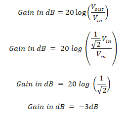
Gain in dB = 20 log (Vout/Vin)
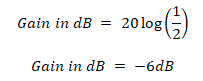
Gain at Cutoff Frequency:
We have established that the output amplitude at the cutoff frequency is 70.7% or (1/√2) of its input max amplitude.
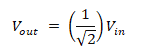
Converting the gain into dB;
Roll Off Rate:
The roll off rate is the rate of change in gain or steepness of the curve in the stop band of a filter. It depends on the order of the filter & it is given by;
20n dB/decade or 6n dB/octave
Where n is the order of the filter.
The decade means 10 times increase in the frequency whereas the octave means 2 times increase in the frequency.
- Related Post: Types of Passive Low Pass Filters
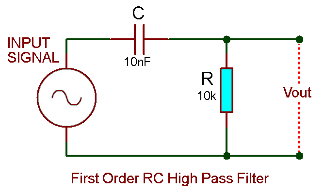
RC First Order High Pass Filter:
In this design of high pass filter, a capacitor is connected with a resistor in series. The input signal is applied through the capacitor. The output is taken across the resistor as shown in the figure.
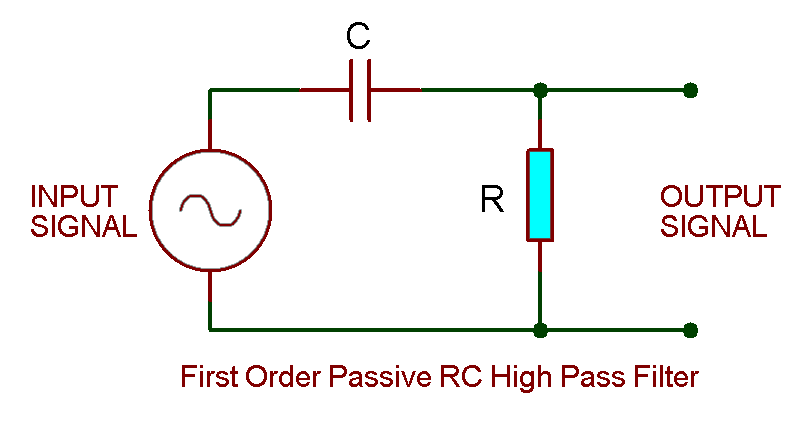
Its design is the same as RC low Pass filter with a minute change of swapping the position of capacitor & resistor.
Operation:
The reactance of the capacitor is very high at low frequency. It acts as an open circuit to low frequency signals. Thus the low-frequency input signal gets blocked and it never makes it to the output terminal as the whole signal appears across the capacitor.
The capacitor’s reactance decreases with increases in the frequency. Therefore it starts allowing the input signal when it reaches a specific frequency.
The reactance of the capacitor plays a major role in this filter’s performance. It depends only on the signal frequency.
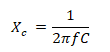
The total impedance of this circuit is;
![]()
- Related Post: Types of Rectifiers and Their Operation
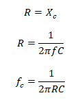
Cutoff Frequency of Passive RC High Pass Filter:
At the cutoff frequency, the resistance and the capacitive reactance of the circuit are equivalent. i.e.
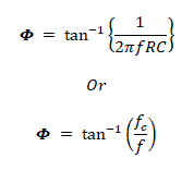
The phase shift φ(phi) of this filter is given by;
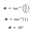
Thus, the phase shift at the cutoff frequency will be always;
Output Voltage;
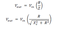
The output voltage for this circuit is given by applying the voltage divider rule;
- Related Post:Types of SSR Relays – Construction & Operation
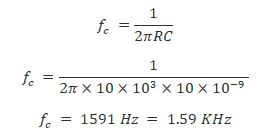
Example of Passive RC High Pass Filter:
Let’s assume the resistor R = 10kΩ & the capacitor C = 10nF.
Calculating the cutoff frequency for this filter;
Let’s verify this cutoff frequency by simulating the given example using Proteus. The frequency response of this example is given below;

The frequency is shown at the bottom left corner and its corresponding gain at the bottom right corner for the selected point on the graph. It clearly shows a gain of -3dB at the frequency 1.59 KHz which is the cutoff frequency of this filter.
- Related Post: Types of Diodes and Their Applications
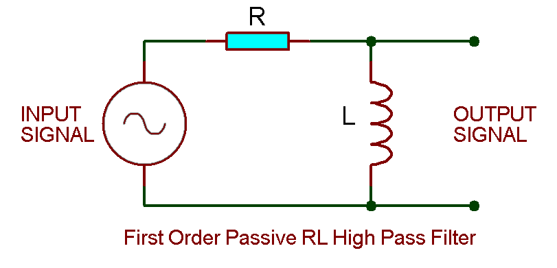
RL First Order High Pass Filter
This filter is designed by combining a resistor with an inductor. The input is applied to the resistor and the output is taken across the inductor as shown in the figure down below;
Operation:
The inductor’s reactance depends on the frequency of the signal. It is directly proportional to the frequency. When a low-frequency signal is applied, the reactance of the inductor becomes very low and it starts behaving as a short circuit. Whereas the resistance of the resistor is relatively very large. Thus the signal only develops across the resistor, leaving a little to no voltage at the output terminal.
When the frequency increases, the reactance of the inductor also increases. Eventually, it overcomes the resistance of the resistor and starts to develop a large portion of the input signal across its terminals.
This is how the low-frequency signal is filtered out through the RL high pass filter.
The Inductive reactance is given by;
![]()
The impedance of this RL circuit is given by;
![]()
- Related Post: Counter and Types of Electronic Counters
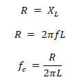
Cutoff Frequency of RL High Pass Filter:
Just like RC filters, RL filters have the same condition for cutoff frequency i.e. the frequency at which the inductive reactance becomes equivalent to the resistance of the resistor.
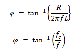
The phase shift φ is given by;
Output Voltage:
Applying the voltage divider rule, the output voltage of the circuit is given by;

Example of First-Order RL High Pass Filter:
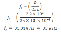
Assume a resistor R = 2.2 KΩ with capacitor C = 10mH.
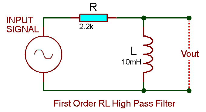
Let’s find its cutoff frequency using its formula;
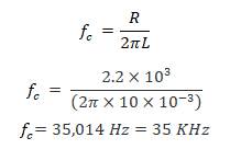
we are going to verify this result using Proteus simulation tool.
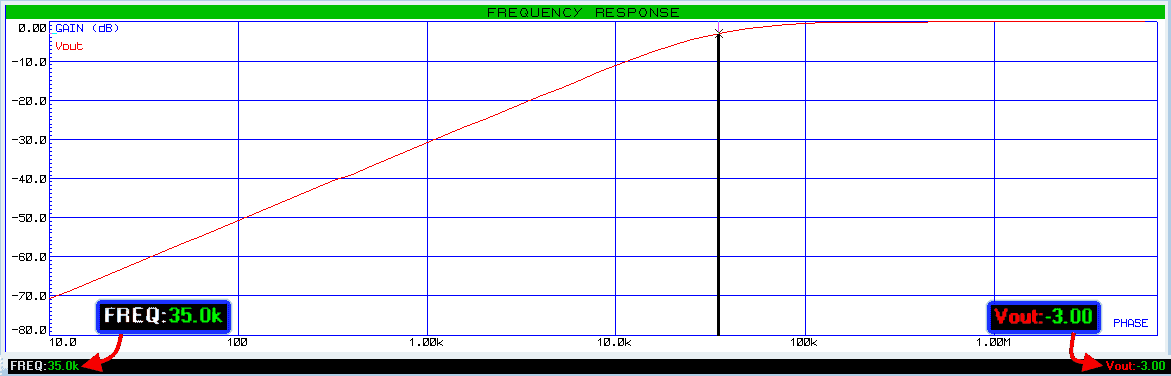
As shown in the frequency graph above, the gain at the frequency of 35 KHz is -3db which is the gain at the cutoff frequency.
- Related Post: Types of Digital Latches – SR D Latches
Second Order Passive High Pass Filter:
The second order filters contain two reactive components. A passive 2nd order filter is made by cascading two 1st order filters. This configuration can be applied to both RC & RL high pass filters.
Key Features of Second Order Filters:
- Roll Off Rate:
The roll off rate of a filter is given by;
Roll Off Rate = 20n dB/decade or 6n dB/octave
Where n is the order of the filter
So the roll-off rate of 2nd order filter is 40 dB/decade or 12 dB/octave. This means that the curve of the 2nd order filter is steeper than a 1st order filter.
- Gain at Cutoff frequency;
The cutoff frequency gain of an nth stage filter is given by;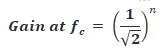
Thus the gain of a 2nd order filter is;

Converting the gain into dB;
Hence the gain of a 2nd order high pass filter at the cutoff frequency is -6b. It also makes sense because the gain of each stage adds up when they are cascaded.
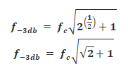
- -3dB Frequency
We know that the gain at the cutoff frequency is -6b which is not the true passband frequency. The passband frequency of any filter lies at gain of-3dB. So the -3dB frequency of an nth order high pass filter is calculated by;
![]()
Where n is the order of the high pass filter.
It determines the stopband and passband frequencies of the filter. Hence, the -3db frequency of a 2nd order high pass filter becomes.
We will use these terms in the example discussed down below;
- Loading effect:
It is the phenomenon of low signal drop at the load circuit due to its low impedance than the source circuit.
Ideally, when evaluating the performance of a multistage filter, we do not consider the input & output impedance of each stage. Practically if the succeeding stage has equal or lower input impedance than the preceding stage, the signal drop will be low at the succeeding stage. This causes an erroneous output.
To reduce the loading effect, the impedance of the succeeding stage should be at least 10 times higher than the preceding stage. It is done by scaling the resistor, capacitor & inductor in both stages of the multistage filters.
- Related Post: Types Of Capacitors | Fixed, Variable, Polar & Non-Polar
RC Second Order Passive High Pass Filter:
Cascading two 1st order RC high pass filters provide a 2nd order filter RC high pass filter as shown in the figure down below.
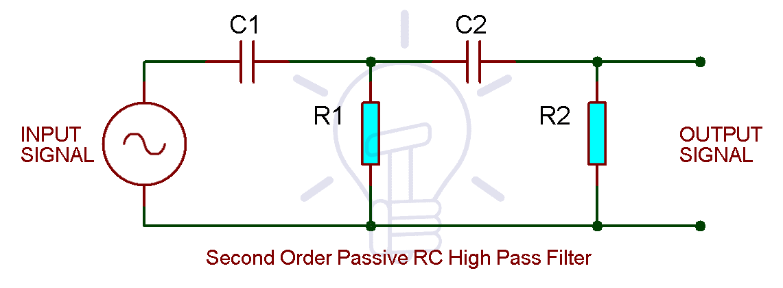
Cutoff Frequency of 2nd Order RC High Pass Filter:
The cutoff frequency of cascading filters depends on both stages & it is given by;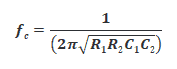
but if the Resistor R1 = R2 & the capacitor C1 = C2, then the cutoff frequency becomes;

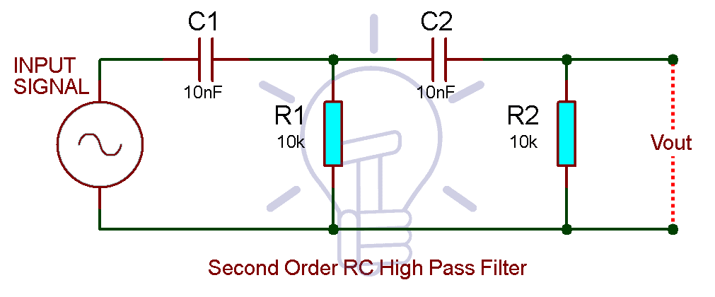
Example of RC 2nd Order Passive High Pass Filter:
Assume the resistor R1 = R2 = 10KΩ & the capacitor C1 = C2 = 10nF.
Scaling the resistor & capacitors to increases the impedance of the second stage;
Increasing the impedance of the 2nd stage by the scale of 10

Decreasing the impedance of 1st stage by 10

The R1’, R2’, C1’, C2’ is the scaled resistor and capacitors. Remember, scaling is done for practical implementation. The scaling factor should be the same for both stages to get the same response. Theoretically, the cutoff frequency for both configurations remains the same.
Now calculate the cutoff frequency fc; 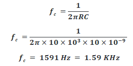
Now, we will calculate its -3dB frequency which is the actual cutoff frequency.

So the cutoff frequency of this filter is 2.47 KHz which lie at the gain of -3dB. We will confirm it by simulating the circuit using Proteus.

It clearly shows a gain of -3dB at the frequency 2.47 KHz & the -6dB point in also highlighted which is at 1.59 KHz.
- Related Post: Different Types of Sensors with Applications
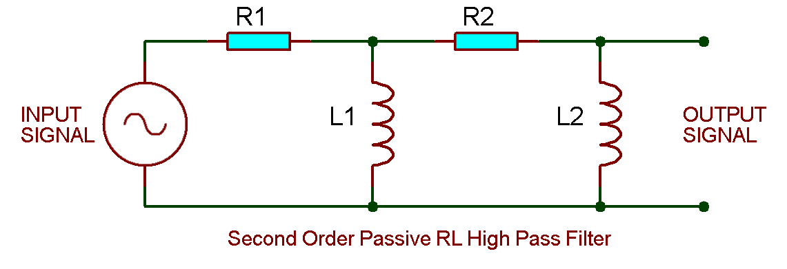
Second Order RL High Pass Filter:
Just like RC filter, cascading two 1st order RL high pass filter will create a 2nd order RL high pass filter as shown in the figure down below.
Cutoff Frequency of 2nd Order RC High Pass Filter
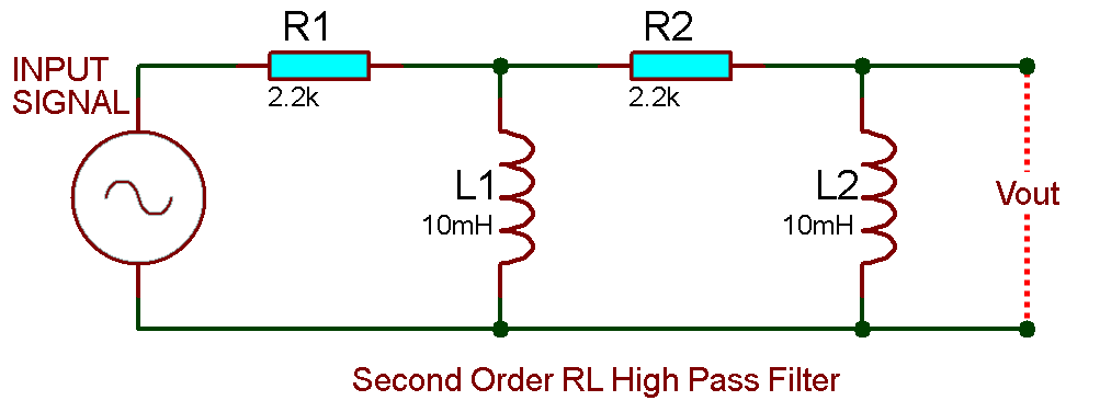
The corner frequency or cutoff frequency fc of 2nd order RL High pass filter is given by.
Or if the inductor and resistors have the same value, then the corner frequency becomes;

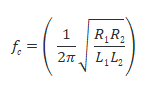
Example of 2nd Order RL High Pass Filter:
We are going to assume the value of resistor and inductor in both stages are same i.e. the resistor R1 = R2 = 2.2 KΩ & the inductor L1 = L2 = 10 mH
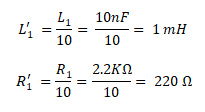
We have taken the same value resistor for the sake simple calculation. Practically you have to increases the impedance of the 2nd stage by scaling the resistors & inductors as shown below;
Increasing the impedance of the 2nd stage by the scale of 10

Decreasing the impedance of 1st stage by 10
Let’s calculate the cutoff frequency of the filter;
But this is the frequency at -6dB & we need -3db frequency of the filter which is the actual cutoff frequency. It is given by;
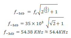
we are going to simulate the given example to verify our results using Proteus tool.
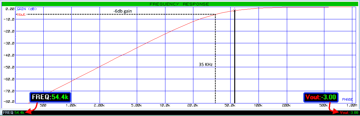
You can see the frequency of 54.4 KHz at the gain of -3db. Also, notice the curve, it is much steeper than the 1st order filter & it has a roll-off rate of 40db/decade.
Related Posts:
- Types of Amplitude Modulation (AM) – Advantages & Disadvantages
- Types of Modulation Techniques used in Communication Systems
- Types of Resistive Sensors – Transducer, Potentiometer & Strain Gauge


