Autotransformer – Its Types, Operation, Advantages and Applications
Autotransformer | Its Operation, Types, Advantages, Disadvantage & Applications
What is Autotransformer:
Autotransformer is a special type of transformer that consists of a single winding. This winding is used for both primary & secondary (High voltage & low voltage) sides. It is widely used for its variable output voltage function, lower cost & small size.
In a conventional two winding transformer, there are two separate windings for high & low voltage side. The connection between these two windings is purely magnetic (mutual induction). It implies that there is electrical isolation between both windings.
On the other hand, Autotransformer utilizes a single winding as primary & secondary at the same time. Due to this, the input & output are connected electrically & also magnetically through self-induction. The electrical connection does include a hazard of removing the isolation between windings but this single winding provides many advantages that are discussed in this article below.
- Related Post: Types of Transformers and Their Applications
Working of Autotransformer:
A standard autotransformer, as shown in the figure below, has one single winding around a laminated core. This single winding is used for both primary & secondary circuit.
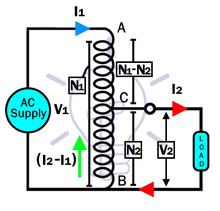
Their winding consists of at least three terminals i.e. A, B & C as shown in the figure. The terminals A & B are fixed terminals while the terminal C is a variable tap point. The AC supply is applied to fixed terminals A & B while the load is connected between variable Tap point C & B.
The autotransformer can have multiple tap points to provide a variable output voltage. Each of these tap points is designed to provide a different turn ratio of the transformer, hence varying the output voltage.
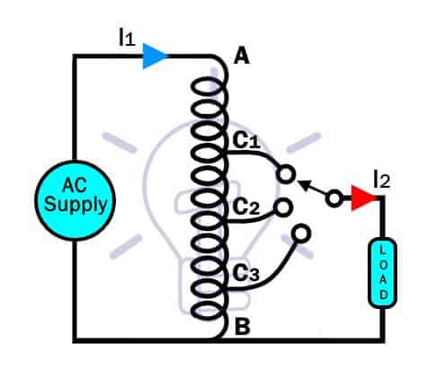
The figure above shows multiple tap points i.e. C1, C2, C3. While the other two terminals A & B is fixed.
Apart from the electrical connection between the primary & secondary, there is an energy flow through induction. That is because of the varying AC current in the winding generates a varying magnetic flux, which induces an EMF in the winding, also known as self-induction. So the output of autotransformer is a combination of energy transformation & electrical conduction, thus it has more efficiency than a conventional two winding transformer but at the cost of no electrical isolation.
The winding from point A to B acts as primary winding while the common winding between C & B acts as the secondary winding. Assume the number of turns in the primary winding is N1 & the number of turns in the secondary winding is N2. So the transformer turn ratio is given by;
Turn ratio, k = N2 /N1
This turn ratio may vary depending on the variable tap point which can increase or decrease the number of turns in the secondary N2.
Assume the transformer has no losses & the voltage supplied to the primary is V1 & the secondary voltage across to the load is V2 then;
V2 / V1 = N2 / N1 = k
V2 = V1 k
V2 = V1 (N2 / N1)
By varying the tap point C in the winding, we can change the turn ratio k. This will result in a variable secondary voltage. So the output voltage of an autotransformer can be varied by moving the tap point.
- Related post: Why Transformer Rated In kVA, Not in KW?
Types of Autotransformers:
Based on increasing & decreasing the voltage, autotransformer is divided into two types i.e. Step up transformer & step down transformer. Just like two winding transformers, a single autotransformer can be used in both configurations.
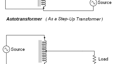
Step Up Autotransformer
Such kind of autotransformer’s output voltage exceeds its input voltage & vice versa for its current.
For performing the step-up function, the AC supply is connected to the variable tap point C & B. while the load is connected to the terminal A & C as shown in the figure down below.
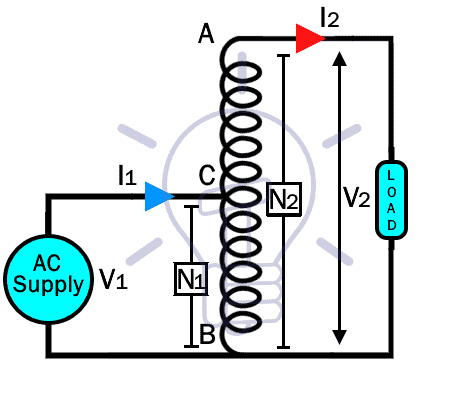
In such configuration, the number of turns in the primary winding N1 (input winding) which between C & B, is less than the number of turns in the secondary winding N2.
So the turn ratio (N2 / N1) becomes greater than one, which is the condition for a step up transformer.
Related Posts:
Step Down Autotransformer
In step down autotransformer, the output voltage is less than the input voltage & the output current is greater than the input current.
In order to perform step down function, the connections are reversed to the step up configuration. The AC supply is connected to the fixed terminals (A & B) of the autotransformer, while the load is connected between terminals C & B.
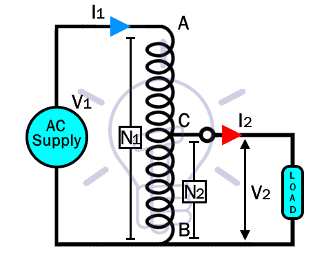
The number of turns in the primary winding N1 between point A & B exceeds the number of turns in secondary winding N2. Hence the turn ratio becomes less than 1, which is the condition for step down transformer.
- Related Post: Difference between Power and Distribution Transformers?
Copper Saving In Autotransformer:
The most prominent feature of the autotransformer is its copper saving compared to a conventional two winding transformer.
Copper weight depends on its length and its cross-sectional area. However, the length of copper in a transformer corresponds to the number of turns and the cross-sectional area corresponds to its current rating. Thus the copper weight in a transformer is;
Weight of copper = N x I
Where N is the number of turns and I is the current flowing through it.
Due to two different currents in the winding of the autotransformer, the winding in divided into two sections i.e. AC & CB.
The copper weight for section AC is;
WAC ∝ I1 (N1-N2)
I1 is the current flowing through it & (N1-N2) is the number of turns between A & C point.
The copper weight for section CB;
WCB ∝ (I2 – I1) N2
N2 is the number of turns between point C & B. The current (I2 – I1) however is because the Load current I2 is opposite in phase to the current I1. As we know that the output voltage decreases because of the lower secondary turns, the output current I2 exceed the primary current I1. So the results of both current become (I2 – I1).
Now the total copper weight of the winding of autotransformer, Wa is;
Wa ∝ (WAB + WBC)
Wa ∝ I1 (N1 – N2) + (I2 – I1) N2
Wa ∝ I1N1 – I1N2 + I2 N2 – I1N2
Wa ∝ I1N1+ I2N2 – 2 I1N2
Now let’s find the copper weight of a conventional two winding transformer;
Copper weight of primary winding;
Wp ∝ I1N1
Copper weight of secondary winding;
Ws ∝ I2N2
The total copper weight of two-winding transformer;
Wtw ∝ Wp + Ws
Wtw ∝ I1N1 + I2N2
Now, the copper weight ratio of autotransformer to the two-winding transformer;
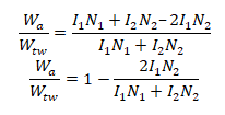
Dividing by I1N1

Now the difference between the copper weight of auto & two-winding transformer is;
![]()
So the copper saving in autotransformer depends on its turn ratio. As the turn ratio of autotransformer remains less than unity, the copper saving increases when the turn ratio reaches near unity.
- Related Post: Power Transformer Protection & Faults
Percentage Copper Saving
The percentage copper saving of an autotransformer can be easily found by taking the ratio of low voltage side to high voltage side. Such as
Percentage copper saving = VL/VH x 100%
As the voltage corresponds the turns in the winding, so the percentage copper saving can also be calculated as;
Percentage copper saving = NL/NH x 100%
Where
NL = number of turns on the low voltage side
NH = Number of turns on the high voltage side
Advantages of Autotransformer:
- The most prominent feature of an autotransformer is that it saves copper. The amount of copper used in an autotransformer is less than a two winding transformer of the same ratings. Thus it reduces the capital required for its construction.
- The single winding used in the autotransformer significantly reduces its size & weight.
- Having small size & weight of the autotransformer, it enables it to have a high VA rating than an ordinary two winding transformer for the same amount of material.
- The voltage regulation is much better than the two-winding transformer because of the elimination of the losses in the second winding.
- Due to the electrical conduction, magnetic induction & reduction in the losses due to the second winding, the efficiency of the autotransformer is higher than the two-winding transformer.
Related Post: EMF Equation Of a Transformer
Disadvantages of Auto transformer:
- There is no electrical isolation between the windings. So grounding the primary of an autotransformer won’t eliminate the risk of an electrical shock as both windings are electrically connected. The circuit will still complete through the ground.
- Due to the electrical isolation present between the winding, two winding transformer blocks the transfer of harmonics between the load & supply, while autotransformer actually can’t.
- Because of the low leakage flux between primary & secondary, the impedance of the autotransformer is low. Thus it may result in large fault currents in the secondary.
Related Post: Maintenance of Transformer – Power Transformers Maintenance, Diagnostic & Monitoring
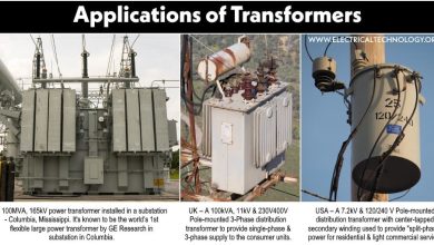
Applications of Autotransformer:
- They are used for the compensation of the voltage drop in the distribution transformers.
- For starting induction & synchronous motors, several methods are used. One of the methods is using an autotransformer.
- A variable autotransformer also known as Variac, which has continuous variable output voltage is used in the laboratories.
- A break in the common winding of the autotransformer will result in full input voltage at the load.
Related Posts:
- Transformer Performance & Electrical Parameters
- Transformers Insulation Materials in Oil-Immersed & Dry Type T/F
- Transformers Fire Protection System – Causes, Types & Requirements
- Advantages and Disadvantages of Three Phase Transformer over Single Phase Transformer.
- Transformer Phasing: The Dot Notation and Dot Convention