Hotel Wiring Circuit – Bell Indicator Circuit for Hotelling
Bell Indicator Circuit Wiring Diagram for Hotelling
Bell indicator circuit is used where a bell and buzzers are needed to control from different locations. Bell Indicator circuit is also known as hotelling circuit where an electric bell is controlled from more than one locations.
In hotel wiring circuit, the bell can be operate from different locations such as rooms by guests.
- Related Wiring Tutorial: Hostel Wiring Circuit Diagram and Working
It can be used to find the exact location and room where the guest needs attendant help. When a guest presses the push button, the specified indicator with room number starts to glow with ringing bell at the hotel management and attendant panel. The room attended then attend the exact room specified by indicator lamp where they seek help.
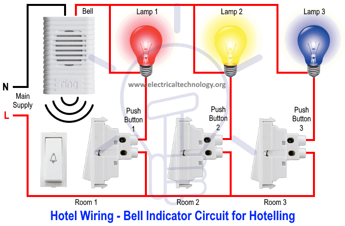
Hotel Wiring or Bell Indicator Circuit
Following is the basic hotel wiring or bell indicator circuit.
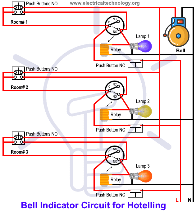
There is one flaw in this circuit as if there in no one in the pantry, They won’t be able to know who need assistance from which room? For this reason, an advanced hotel wiring circuit can be made with the help of 2 nos of NO (normally open) 230 or 120V contact blocks for one push button, 2 nos of NC (normally closed) push / release buttons for 1 room, 230V or 120V relay coil (NO) and 1.5mm 2 wires for phase and neutral.
This way, when a guest press the push button, the indicator bulb and bell will ring until someone in the reception switch off the bell and indicator lamp by pressing the push button installed on the panel board. This way, it makes sure some one in the pantry is aware and going to attend the guest in the specified room.
Here is another bell indicator circuit for hotelling.
Requirements:
| Component | Rating | Quantity |
| MCB | 120V or 230V, 5A | 1 |
| Bell / Buzzer | 120V or 230V | 1 |
| Push Button | SPST, 5A | 3 |
| Light Bulbs | 40W, Three Colors | 3 |
| Wire Size | According to the rating | 2 |
Procedure:
- First of all, turn off the main breaker to ensure the main supply is switched OFF.
- Connect the neutral wire directly from CB to to first terminal of electric bell or buzzer.
- Connect all the push button switches lower terminals to the line (phase or live) wire from related circuit breaker.
- Connect the upper terminals of push button switches to the first terminal of indicator lamps or bulbs.
- Connect the second terminals of all indicator lights bulbs through a common wire and wire them to the second terminal of electric bell.
- Do the proper earthing and grounding according to your local area codes.
Related Wiring: Godown Wiring Diagram – Tunnel Wiring Circuit and Working
Working:
The bell indicator circuit used in hotels and restaurants where the bell and different colors bulbs or assigned number to the lamps are configured in a panel installed in reservation and reception. The indicator lamps and bell are controlled from different location by push buttons switches.
For example, when a guest press the push button in room 1, the circuit completes which leads to glow the indicator bulb and bell rings. This way, the attendant know the exact room (specified by assigned number or color to the lamps) and manage him accordingly.
The circuit follow the above sequence for other rooms i.e. pressing any push button will complete the circuit, bell rings and bulbs start to glow.


Working of the hotel circuit diagram can be understand by the following animated gif and video.

You may use to the above circuit in many rooms and control the bell from many locations. Just add the push button switches and connect them to the bell and associated indicator lamps.
Video:
Note: Use the suitable voltage and ampere rating of switch with appropriate wire size and proper size MCB according to the load rating.
Related Post:
- Staircase Wiring Circuit Diagram and Its Working
- How to Control One Lamp From Two or Three Places?
- How to Control a Lamp by a Single Way or One-way Switch?
- How to Control One Light Bulb from Six Different Places?
- What is Intermediate Switch & Its Construction, Working & Uses in Electrical Wiring
- How To Wire Switches In Series?
- How To Wire Switches in Parallel?
- How To wire Lamps in Series?
- How To Wire Lamps in Parallel?
- Which Bulb Glows Brighter When Connected in Series and Parallel & Why?
- Even more Home Electrical Wiring Installation Diagrams & Tutorials


All three Circuit Diagrams and Explanation of how it Works is very Good and Interesting and I would like other Information and keep Up to Date with what You do.
Thank you. We will add more wiring circuit diagrams in the coming days. Stay tune. Regards.
Thank you for the diagrams you have been sending. Kindly continue sending more
Victor Opati
hello sir kindly am Godfrey James an electrician from Kenya in a county called Homabay 19years old now .
looking forward to work with you