How to Wire Combo Switch and Outlet? – Switch/Outlet Combo Wiring Diagrams
Switch and Outlet Combo Device Wiring Diagrams and Installation
What is Combo Switch/Outlet Device and How to Wire It?
A combo device is the combination of switch and outlet in the same enclosure box. The built-in switch can be wired to control the receptacle in the enclosure box. The switch can be also wired through a jumper wire where the switch will control an additional load point such as lighting point.
Before wiring installation of a combo device, one must know the basic different between Combo GFCI and Combo switch outlet. There is a break away fin tab intact to the line terminals of normal combo switch and outlet whereas, it doesn’t exist in GFCI or AFCI combo device. In addition, there is Test and and reset buttons on GFCI combo switch / outlet and one side can be used as line (source) terminal and the second one as load terminals i.e. the those load points which needs to be protected should connect to the load terminals of GFCI.
- Related Post: How to Wire a Pilot Light Switch?
In Switch and Outlet combo device, the narrow blade is for Line (Hot) and the wider blade is for Neutral. There is a break way fin tab intact to the line (hot) side which can be removed if switch is needed to control additional load otherwise, a jumper wire can be added between the switch load terminal and lower line terminal (while removing the break away fin tab) hence, it will control the socket outlet in the enclosure box.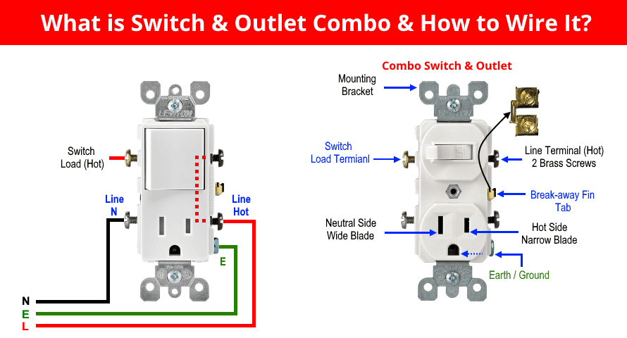
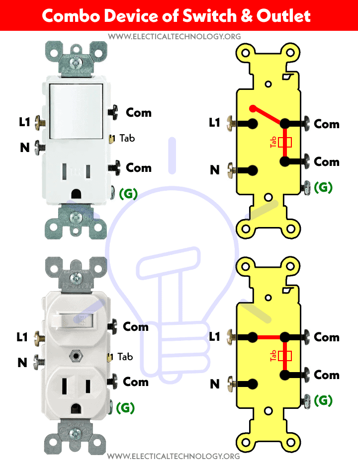
The following diagram shows the the working operations of a Combination of two Switch & Outlet device.
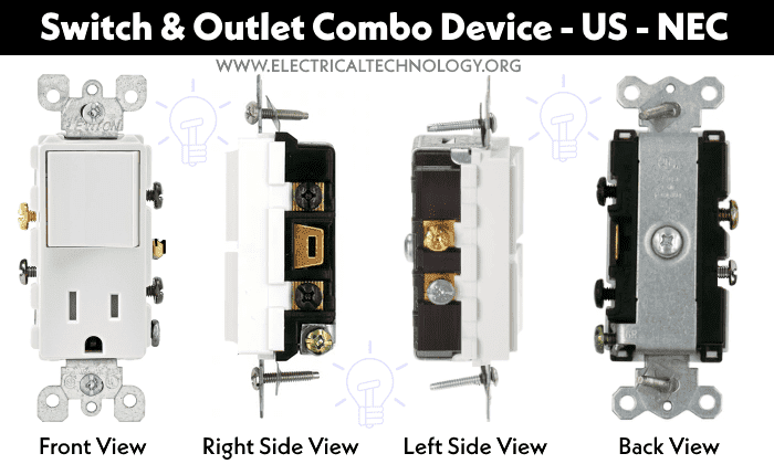
The following figures show the different views of a combo switch & outlet device.
In today wiring tutorials, we will be showing how to wire and install a combo switch and outlet device in residential areas to control the lighting point, adding an outlet to the existing combo device, connecting switch and outlet from different sources, adding a GFCI protected combo switch/outlet and use the switch in the combo device to control the outlet in it.
Wiring a Light bulb with Combo Switch and Outlet
In this simple wiring diagram, the combo switch & outlet is connected to the 120V AC supply through CB. The break away fin tab is intact therefore, line (hot) is connected to the (only) one brass terminal on line side. The neutral is connected to the neutral silver terminal. The switch load brass terminal and neutral is connected to the light bulb.
This way, the built-in switch controls the lighting point and socket outlet can be used for other loads and can be connected via plugs.
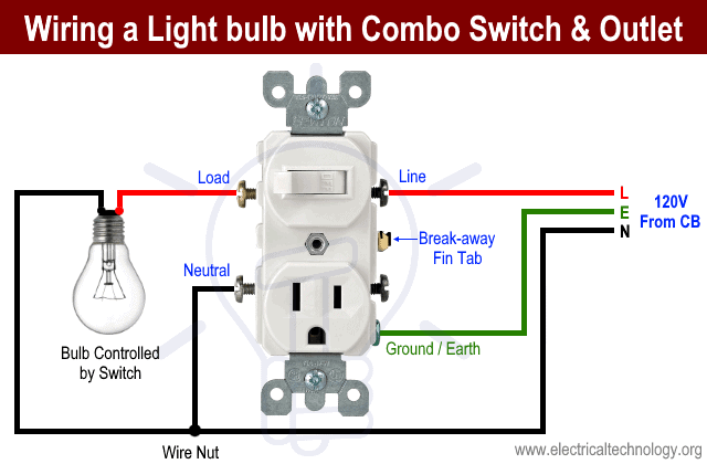
Also, don’t forget to do the proper earthing and grounding connections according your local area codes.
Related Wiring:
- How to wire a GFCI Outlet? – GFCI Wiring Circuit Diagrams
- How to Wire an AFCI Outlet? – AFCI Wiring Circuit Diagrams
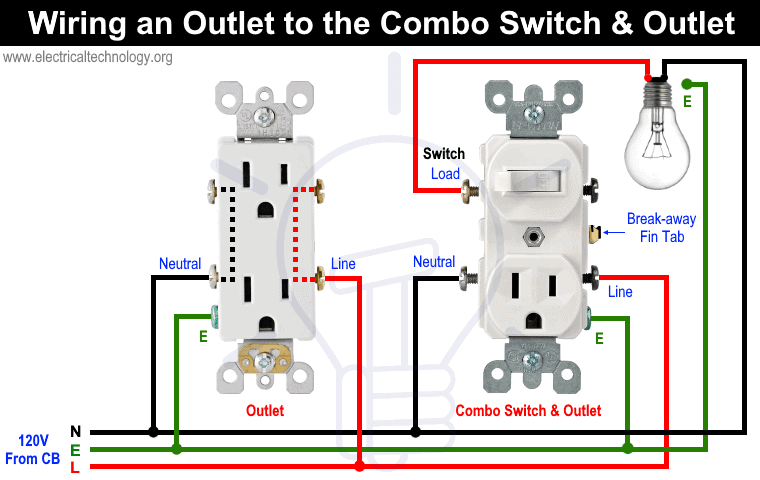
Wiring an Outlet to the Combo Switch & Outlet
In this wiring diagram, the builtin switch in the combo device controls a lighting point whereas, outlet can be used for other loads. To add an additional outlet to the combo device, simple connect the line, neutral and ground terminals as shown in the fig below. Use tight wire nuts for cable and wire joints.
Related Posts:
Wiring Combo Device where Switch & Outlet Controlled by Different Sources
In this wiring diagram, the built-in switch is controlled by separate source (i.e. wires from different CB) while the outlet is connected to the second source. To do this, simple remove the breakaway fin between the line terminals and connect the upper terminal to source one and the lower line terminal to source two.
The lower neutral should be connected to the source two neutral wire and the switch load should be connected to the load point i.e. fan, light bulb etc.
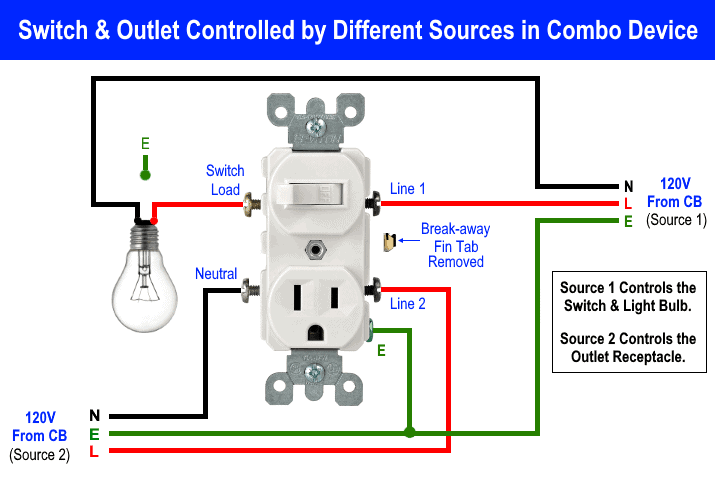
Keep in mind that if the break away fin tab is not available in your existing or new combo switch-outlet device, then this kind of wiring connection is not possible.
Related Posts:
Wiring Combo Device where Built-in Switch Controls the Receptacle in it
In this wiring connection, the built-in switch controls the receptacle outlet in the combo device enclosure. To do this wiring, simply remove the break away fin tab between two hot terminals (hot side). Now, take a jumper wire and connect between the switch load terminal and lower hot terminal on the line side (As shown in fig below). Finally, connect the neutral and ground wire as shown in the fig.
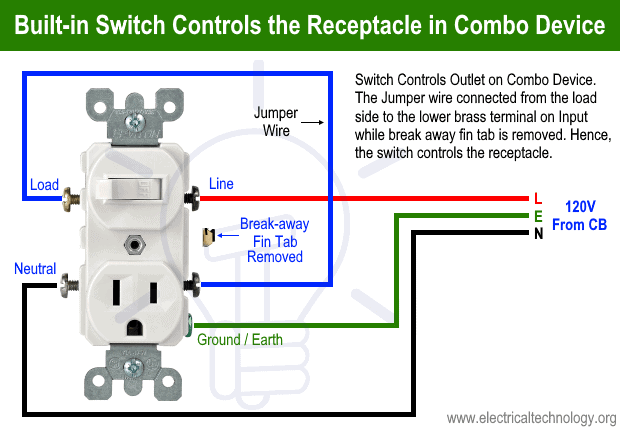
This way, the builtin switch control the ON/OFF operations of the receptacle in the combo device. Note that if there is no break away fin tab between two line terminals, this connection is not possible to do then.
Wiring a GFCI Protected Combo Switch & Outlet
As discussed in the previous post here, any receptacle outlet, switch and combo device connected to the load side of a GFCI are ground faults protected.
As shown in the following wiring diagram, the combo switch & outlet, ordinary outlet and switch are connected to the load side of GFCI hence, all of them are GFCI protected.

Keep in mind that if we connected all these receptacles and switches to the line side of GFCI, they wont be GFCI protected at all.
Related Posts: How to a Wire 3-Way Combination Switch and Grounded Outlet?
General Information about Electrical Outlets:
Note: We have used Red for Hot, Black for Neutral and Green for Ground for illustration purpose only. Follow your own area wiring color codes according to NEC, IEC etc.
- Use 14 and 12 gauge wires for 15A and 20A circuit breakers.
- 15A and 20A GFCI can be installed on 15-20A and 20A only (not 15 and 30A) circuit breaker respectively.
- The brass screws should be connected to the Hot (line, live or phase) wire (Black, Brown or Red).
- The silver screws should be connected to the Neutral wire (White or Blue)
- The green screw should be connected to the ground / earth wire (Green/Yellow or naked)
- If there is no color coded screws on outlets, refer to the user manual or contact a licensed electrician.
- Neutral Wire is not required in 240V outlets wiring.
- If there are four prongs in an outlet, a Neutral wire is needed then and four wires from the breaker should be connected to the outlet i.e. 2 hot line as (Line 1 and Line 2), a Neutral and ground wire.
- Use the suitable voltage and ampere rating of switch with appropriate wire size and proper size MCB according to the load rating.
Precautions:
- Switch off the main circuit breaker to make sure the power supply is OFF before wiring an outlet.
- Contact the authorized and licensed electrician for outlet installation if you are not sure about the wiring diagrams.
- The author will not be liable for any losses, injuries, or damages from the display or use of this information or if you try any circuit in wrong format. So please! Be careful because it’s all about electricity and electricity is too dangerous.
Related Electrical Wiring Installation Tutorials
- Wiring of the Distribution Board with RCD (Residual Current Devices)
- Corridor Wiring Circuit Diagram – Hallway Wiring using 2-Way Switches
- Tunnel Wiring Circuit Diagram for Light Control using Switches
- Hospital Wiring Circuit for Light Control using Switches
- Hotel Wiring Circuit – Bell Indicator Circuit for Hotelling
- Hostel Wiring Circuit Diagram and Working
- Godown Wiring Diagram – Tunnel Wiring Circuit and Working
- Difference Between MCB, MCCB, ELCB & RCD Circuit Breakers
- Even More Electrical Wiring Installation & Tutorials


More about switch, lighting one bulb with three switch
Thank you for feedback… New electrical wiring tutorials will be added very soon. Stay tune and subscribe to our mailing list so that, you will get each update in your email inbox.
I can’t read your diagrams because there’s too many advertisements on the page
The article is an exceptional resource for anyone interested in electrical technology. It stands out for its comprehensive and clear explanations of how to wire a combo switch outlet. The step-by-step instructions provided are easy to follow, making it an invaluable guide for both beginners and experienced individuals. Additionally, the inclusion of diagrams and visuals enhances the understanding of the concepts, ensuring a smooth and successful installation process. This article not only promotes safety by emphasizing the importance of proper wiring techniques but also empowers readers to confidently tackle electrical projects. Overall, it’s an excellent and uniquely informative resource that deserves recognition for its valuable content.