Hospital Wiring Circuit for Light Control using Switches
Light Control Circuit by Switches for Patient in Hospital Rooms
We call it “Hospital wiring circuit” by using only switches and lamps to control the lighting density of bulbs in a room especially for admitted patients in the hospital. Although, we can control the lighting density by using a light dimmer switch with led lamps or PWM controller with LED. In this circuit, we only use normal ON/OFF switches to control the lighting in three ways i.e. Maximum light, Medium light and Minimum light.
- Related Wiring Tutorial: Hotel Wiring Circuit – Bell Indicator Circuit for Hotelling
Hospital Wiring Circuit for Light Control
Following is another wiring circuit for light control using light dimmer switches. Keep in mind that light dimmer switches will work only with dimmable led lamps while non-dimmable light lamps wont work with dimmer circuit and switches.

- Related Wiring Tutorial: Godown Wiring Diagram – Tunnel Wiring Circuit and Working
Requirements:
| Component | Rating | Quantity |
| MCB | 120V or 230V, 5A | 1 |
| One – Way Switch | SPST, 5A | 1 |
| Two – Way Switch | SPDT, 5A | 1 |
| Light Bulb | 40W | 2 |
| Wire Size | 1.2mm PVC | 2 |
Procedure:
- First of all, turn off the main breaker to ensure the main supply is switched OFF.
- Connect all the switches to the earthing / grounding terminals (not shown in the fig)
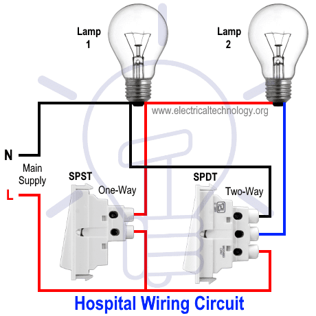
- Connect the Neutral wire from MCB directly to the first terminal of lamp # 1 and then connect to the upper terminal of SPDT (2-Way) switch as shown in the fig.
- Connect the live (line or phase) wire to the lower terminals of SPST (1-way) and SPDT (2-way) switches.
- Connect the lamp # 1 to the upper terminal of SPST switch.
- Connect the lamp # 2 to the common (middle) terminal of SPDT switch shown by blue wire in the circuit diagram.
- Do the proper earthing and grounding according to your local area codes.
- Now turn on the main breaker to ensure the circuit is working properly according to your needs.
Related Wiring Tutorial: Hostel Wiring Circuit Diagram and Working
Working:
The hospital circuit for lighting control is working as follow:
- No Light:
SPST OFF and SPDT Up. Both lamps are turned OFF as the circuit is not completed yet.
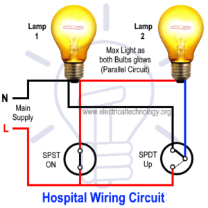
- Maximum Light:
SPST ON and SPST Up. Both lamps are glowing at rated density as both bulbs are connected in parallel and getting the rated voltage.
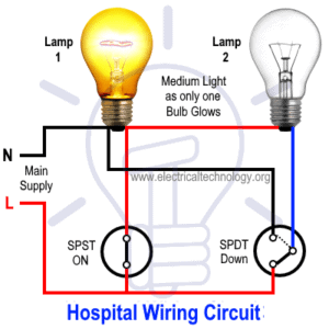
- Medium Light:
SPST ON and SPST Down. Only one lamp is turned ON. The first lamp is glowing while the second one is turned OFF.
- Minimum Light:
SPST OFF and SPST Down. Both lamps are dim i.e. they are connected in series and getting half of the rated voltage.


The working and operation of hospital wiring circuit is shown in the following animated fig as well as video.
Video:
Note: Use the suitable voltage and ampere rating of switch with appropriate wire size and proper size MCB according to the load rating.
Related Post:
- Staircase Wiring Circuit Diagram and Its Working
- How to Control One Lamp From Two or Three Places?
- How to Control a Lamp by a Single Way or One-way Switch?
- How to Control One Light Bulb from Six Different Places?
- What is Intermediate Switch & Its Construction, Working & Uses in Electrical Wiring
- How To Wire Switches In Series?
- How To Wire Switches in Parallel?
- How To wire Lamps in Series?
- How To Wire Lamps in Parallel?
- Which Bulb Glows Brighter When Connected in Series and Parallel & Why?
- Even more Home Electrical Wiring Installation Diagrams & Tutorials


Good
The technical information furnished is very useful and informative.
Thanks
Hi. Thank You, from Colombia. Very importan your information. REGARDS.
Can one lamp be used with this type of wiring.also can we used more than two lamp?
For single lamp, You can use dimmer switch with dimmaable LED lamp. Thanks
This is a clever circuit, but against code as it could leave the neutral part of the lamp socket energized with a potential to ground. This could electrocute someone who might unscrew a bulb that is off and that they think has no power if they touch the metal part of the bulb while unscrewing it (SPST on, SPST down). Super dangerous. Don’t do this. Also, considering SPDT switches are more expensive, it’s probably better going with a dimmer. And LEDs save energy.