Alternator or Synchronous Generator: Construction, Working, Types & Applications
Alternator or AC Generator: Construction, Working, Types and Applications
Have you ever wondered, where does the electrical power come from in vehicles? The answer is “Alternator”. Yes, there is a battery, but that is only used to power the starting of the vehicle. An alternator is a type of generator that converts mechanical energy into electrical energy. The output of the generator can be either alternating current AC or direct current DC. An alternator is a type of AC generator that generates alternating current.
But wait. Vehicles are powered by direct current DC not alternating current AC. Then why do we use an alternator? Well, the alternator has several advantages over a DC generator or dynamo such as lightweight and robustness, etc. whereas its AC output can be easily converted into DC using diode rectifiers since it has lower loss than commutator brush drop in a DC generator. It is explained in below with details
What is Alternator?
An alternator is an electrical machine that converts mechanical energy into electrical energy in the form is alternating current AC. It is also known as a synchronous generator or AC generator (there are other types of AC generators). It generates a specific voltage at a specific frequency.
Good to know: Alternator or synchronous generator is the same machine as synchronous motor except the power flow diagrams and reverse operation e.g.
- Synchronous generator (alternator) converts the input mechanical power into output electrical power
- Synchronous motor converts the input electrical power into output mechanical power.
Related Posts:
- Induction Generator or Asynchronous Generator: Construction & Working
- Synchronous Motor: Construction, Working, Types & Applications
Construction of Synchronous Generator
Unlike DC generator that has rotating armature winding and a stationary magnetic field. The alternator is made of a stationary armature winding and a rotating magnetic field. The field windings are placed in the rotor while the armature windings are placed in the stator.
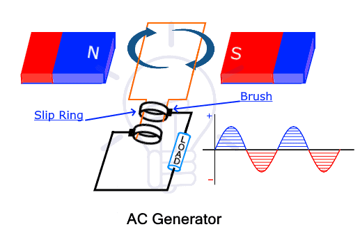
The rotor field windings are connected to an external DC supply with the help of slip rings and brushes. A prime mover rotates the rotor using a pulley and belt. The rotating rotor generates changing magnetic field. This varying field generates end in the armature windings and supplies it to the load or circuit through its terminals.

The different components of the alternator are explained in detail down below.
Components of Alternator or AC Generator
The alternator is made of different stationary and moving components each serving its own purpose. The components of the alternator are given below
Rotor
The rotor is the rotating part of the alternator. It is made in a cylindrical shape that has copper windings also known as field winding. The field windings are electromagnets that generate the necessary rotating magnetic field when rotated. Rotor has a shaft that is rotated using a drive belt pulley system. The source that rotates the rotor is called a prime mover. It can be anything such as an engine, water turbine, wind turbine, etc.
There are two types of rotors used in alternators or synchronous generators.
- Salient Pole Type
- Cylindrical Pole Type
Salient Pole Type: it is a type of rotor that has a large number of protruding or projecting poles mounted on a core made of magnetic laminated steel or cast iron. The term salient refers to protruding or projecting as shown in the figure below.

The salient poles are made of laminated steel or iron cast of good magnetic properties to reduce the Eddy current losses. The pole shoes have multiple slots for damper winding that helps in preventing haunting. The field coils are wounded across the poles and then connected in series. The field coil is energized by connecting its ends to a separate DC source through a pair of slip rings. The slip ring and brushes are mounted on the shaft of the rotor.
The salient pole rotor has a large diameter and small axial length. They are used in low and medium-speed alternators such as in hydropower stations. They are not suitable for high speed due to the increased windage loss at high speed due to their design (salient poles). Its design does not have enough mechanical strength to handle high speed.
Cylindrical Type: such type of rotor has very few 2 or 4 poles. It is made up of a laminated steel cylinder. The cylindrical rotor has slots for field winding that is connected in series. The poles are left unslotted as shown in the figure below. Since the poles are not protruding out of the core, it is also known as a non-salient pole or round rotor. it has very few and non-salient poles, therefore its rotor diameter size is small while its axial length is longer than the salient pole rotor.

The cylindrical design provides mechanical strength, robustness and uniform distribution of magnetic flux. It has lower windage loss. Therefore it is suitable for high-speed, noise-less operation. They are designed for high-speed alternators such as in thermal power stations
Stator
A stator is the stationary part of an electrical machine. In an alternator, it is used for holding the armature winding that generates the induced emf. The core itself is made of laminated steel or cast iron of good magnetic quality to reduce Eddy current losses. The rotor that carries the field windings rotates inside the stator without physically touching it.

On the contrary, the DC generator’s stator holds the magnets to generate the necessary magnetic field. The alternator’s stationary armature winding has huge advantages over the DC rotating armature as given below
- Rotary armature requires brushes that have a larger voltage drop at high voltage.
- The fraction and sparks from brushes damage and reduce their life span as well as require frequency maintenance.
- The stationary armature has no moving parts, thus output current is directly drawn from its terminal without the brushes and the included losses.
- It is simpler to design and insulate stationary armature winding for high voltages.
- The armature winding can be braced mechanically better to withstand the electromagnetic and centrifugal forces.
- Small DC voltage can be used to safely energize the rotor field winding using slip rings.
Yoke
The yoke is the outermost part of the alternator that is used to provide mechanical support and protect the inner parts from environmental conditions that can damage it.
Slip Ring and Brushes
A slip ring is a component that transfers electrical power between stationary and rotating parts of a machine. In an alternator, it is used to transfer DC power to the rotor field windings from a DC battery using brushes that slide over the slip ring. It is made of concentric discs placed on the shaft of the rotor. As it supplies DC, the alternator only requires two slip rings.
The DC current flow through the field winding generating the magnetic field that varies with the rotation of the rotor.
Diode Rectifier
Diode rectifier is two terminal semiconductor component used for the conversion of alternating current AC into unidirectional direct current DC. There are 6 diodes used two per phase to convert into smooth DC. Remember, it is only used in alternators that require DC output such as in automobiles and submarine
Voltage Regulator
A voltage regulator (AVR) is used to monitor the output of the alternator and adjust its voltage by adjusting the energizing current to the rotor. The alternator’s output is feedback into the rotor through the voltage regulator. It maintains constant output voltage regardless of the rotor speed of the alternator.
Pulley and Belt
A pulley and belt are used to connect the rotor with the prime mover such as the engine or turbine. It rotates the rotor at high speed to create a varying magnetic field.
Drive End Bearing
Bearing is used to reduce friction and transfer maximum energy to the shaft from the pulley. It enables smooth rotation.
Related Posts:
- Single-Phase Induction Motor – Construction, Working, Types & Applications
- Three-Phase Induction Motor – Construction, Working, Types & Applications
Working of Alternator
An alternator or synchronous generator works on the principle of the Faraday law of electromagnetic induction just like in other AC generators. It states that whenever a conductor moves in a magnetic field, an EMF (electromotive force) or current is induced in the conductor which can be found using the EMF equation of an alternator. In other words, a conductor placed in a varying magnetic field also experiences EMF and it is used in alternators.
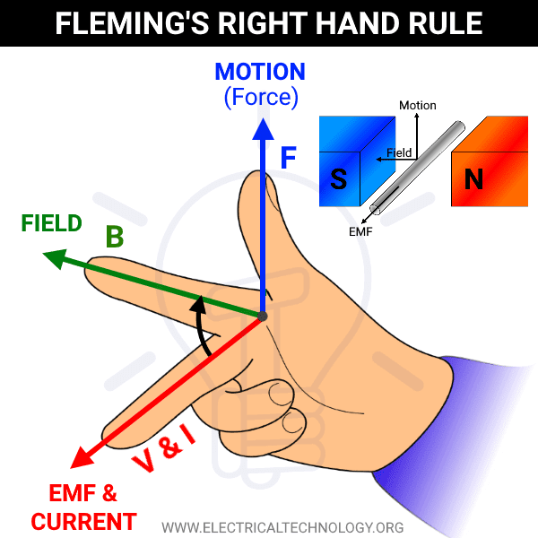
The direction of the induced current is determined by Fleming’s right-hand rule. If we arrange the thumb, forefinger and middle finger of the right hand, the thumb direction of motion, the forefinger represents induced current and the middle finger represents the direction of magnetic field lines. Therefore, they are all mutually perpendicular.
The conductor is formed into a coil of multiple turns called armature winding. In the alternator, the armature is stationary. Therefore, it is placed inside the stator. The field windings are used for generating a magnetic field. Since the field is moving, field windings are placed inside the rotor. The field windings are energized through slip rings to form an electromagnet having north and south poles.
The rotor rotates with the help of a prime mover. The magnetic field poles also rotate at the same speed as the rotor. Thus the varying magnetic flux cuts the armature winding inducing current in the windings.
The induced EMF depends on the alignment of the magnetic field and armature winding. It is maximum when the armature winding and the magnetic field lines are perpendicular and it is zero when it is in the same alignment. As the magnetic field rotates, the output swings between zero and maximum as in alternating current AC.
The stator has separate armature windings for each phase placed at exactly 120° displacement. Therefore the induced EMF is 120° apart as in a 3-phase alternating current as shown below.

The frequency of the induced EMF depends on the speed as well as the number of poles. It is given by
f = NP/120
Where
- f = frequency of induced EMF
- N = rotor speed in RPM
- P = number of poles
Related Posts:
Types of Alternators
Alternators can be classified based on various factors.
Based on rotor design, alternators are classified into two types
- Salient Pole Type
- Cylindrical Pole Type
Salient Pole Type
The salient pole rotor type alternator has a large number of protruding poles which is explained above in detail. The field winding is wounded around these poles forming N and S poles. Such alternators are used for low and medium speed. Its rotor design cannot support high speed due to Windsor losses. These alternators have a large diameter and small axial length.

Cylindrical Pole Type
Such an alternator has a cylindrical rotor with slots for field winding. The unslotted part of the rotor forms the N and S poles. They are fewer in number usually 2 or 4. It has a smaller diameter and longer axial length. The advantage of such alternator is that it has uniform flux distribution, and high-speed operation.

The alternators are also classified by is output
- Single-phase alternator
- Two-phase alternator
- Three-phase alternator
Single-phase Alternator: Single phase alternator has multiple armature coils connected in series to form a single winding. The single phase output is taken across both terminals of the armature winding.
Two-phase Alternator: Two-phase alternator generates two-phase output. It has two separate armature windings. The armature windings are placed in such a way when one winding has maximum flux, the other has zero flux. Each winding generates a single phase output where both phases have a 90° phase difference as shown below.

It has four output terminals, two per phase The two-phase alternators are early inventions designed for self-starting motors in the early 20th century. With the invention of the three-phase alternator, it replaced the two-phase alternator due to multiple reasons such as less number of conductors required for carrying the same current.
Three-phase Alternator: in the three-phase alternator, there are three armature windings whose output voltage is 120° apart. It has three output terminals each for a separate phase.
Alternators can also be classified based on their applications.
Automotive Alternator: the automotive alternator is used in automobiles. Since vehicles run on DC not AC power, the automotive alternator has built-in rectifiers to convert AC into DC. They are small, lightweight, and specifically designed for charging vehicle batteries and powering electronics in a vehicle.
Diesel-electric locomotive alternator: such alternators are designed to run on diesel engines in a locomotive. It provides power to the traction motor. It also provides AC power to the passenger train for lighting, air conditioning, heater, power outlets, etc.
Marine Alternator: Such alternators are designed to be used in marine and navy boats. It provides charge to the battery and loads on the boat. It uses silicon rectifiers to convert AC into DC. The output of a marine alternator is between 12 to 24 volts.
Brushless Alternator: in such an alternator, the rotor’s slip rings and brushes are replaced by a separate alternator called an excitation alternator. In the excitation alternator, the armature is in the rotor and the field windings are in the stator. The field winding is excited by AVR (Automatic Voltage Regulator) while the rotor’s armature generates current to energize the field windings of the main alternator.
There are no moving parts and It has less wear and tear. Thus it requires less maintenance. It is used in power generation in thermal, hydel, and nuclear power plants.
Radio Alternator: Radio alternator also known as the Goldschmidt alternator is a high-frequency alternator used for generating radio frequency current in radio transmitters. It differs from an ordinary alternator by having a very high speed and many poles around 300 to 600. It was used for generating up to 100 kHz.
Related Posts
- EMF Equation of an Alternator and Synchronous Generator
- Why are Generators and Alternators Rated in kVA, Not in kW?
Advantages & Disadvantages of Alternator
Advantages
Here are some advantages of an alternator
- An alternator has a stationary armature thus the output is taken directly from its terminals without brushes and slip rings.
- There are no electric sparks and wear tear due to friction between the slip ring and brushes, thus it requires less maintenance.
- There is no brush’s voltage drop that increases with an increase in the output voltage.
- It has higher efficiency and higher voltage than a DC generator.
- The rotor field winding is powered by low DC voltage, thus they last longer.
- It has a lower weight, is more compact, and is smaller in size.
- Its design allows it to be used for high-speed and smooth operation.
- It uses a diode rectifier that has a lower voltage drop than a commutator with noiseless and smooth DC output.
- It has a simple and robust design and cheaper than a DC generator.
Disadvantages
Alternators do not have many disadvantages. However, here are some disadvantages of an alternator.
- It requires an efficient cooling system as the large current can overheat it which reduces its performance
- It requires a diode rectifier to convert AC into DC whereas the generator can generate both AC as well as DC.
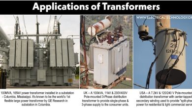
Applications of Alternators (Synchronous Generators)
Alternators, which are synchronous generators, have a wide range of applications, primarily revolving around the conversion of mechanical energy into electrical energy. Some common applications include:
- Power Generation Plants: Alternators are commonly used in power plants to generate electricity. They are often driven by steam turbines, gas turbines, or diesel engines.
- Automotive & Locomotive: Alternators are used in vehicles to charge the battery and power the electrical system when the engine is running. They have largely replaced older generators in this application due to their higher efficiency and reliability.
- Aircraft & Radio Frequency Transmission: Alternators are used in aircraft to generate electricity for onboard systems, including avionics, lighting, and other electrical components. They are often driven by the aircraft’s engines.
- Industrial Applications: Alternators are used in various industrial applications to provide electrical power for machinery, equipment, and other systems.
- Standby and Emergency Power: Alternators are used in standby and emergency power systems, such as backup generators, to provide electricity in case of power outages or other emergencies.
- Renewable Energy: Alternators are used in some renewable energy systems, such as wind turbines and hydroelectric plants, to generate electricity from natural sources of energy.
-
Marine and Navy Boats Applications: Alternators are used in marine applications to generate electricity for ships and boats, often driven by the main engine or auxiliary engines.
Related Posts:
- How to Size a Generator? Portable, Backup & Standby for Home & Commercial Applications
- How to Connect a Portable Generator to the Home Supply – 4 Methods
- Losses in Alternator – Power Stages in Synchronous Generator
- Losses in a DC Generator – Power Stages & Efficiency of DC Generator
- What is Motor Generator Set and How Does it Work?
- Emergency Generator Set – Construction, Installation, Maintenance & Wiring
- Parallel Operation of DC Generators – Synchronization of Generators
- Generator Protection – Types of Faults & Protection Devices
- Synchronous Generator and Alternator Formulas & Equations
- DC Generator Formulas and Equations
- Generator and Alternator Symbols