Stepper Motor – Types, Construction, Operation and Applications
Types of Stepper Motors: Construction, Working, and Applications
The invention of dedicated stepper motor driver cards and other digital control technologies for interfacing stepper motors with PC-based systems has led to their widespread acceptance in recent times. Stepper motors have become the ideal choice for automation systems that require precise speed control, precise positioning, or both.
While many industrial electric motors use closed-loop feedback control for achieving precise positioning or speed control, a stepper motor can operate on an open-loop controller. This reduces the total system cost and simplifies machine design compared to servo system control. Let’s briefly discuss different types of stepper motors.
What is a Stepper Motor?
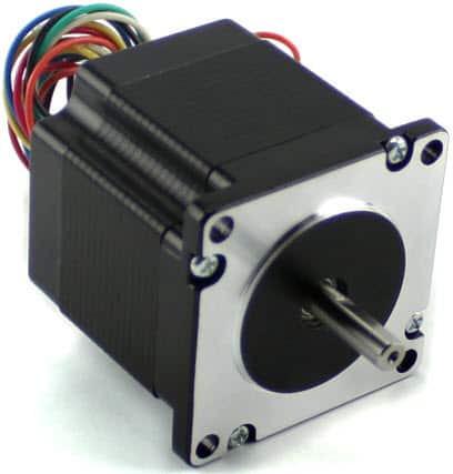
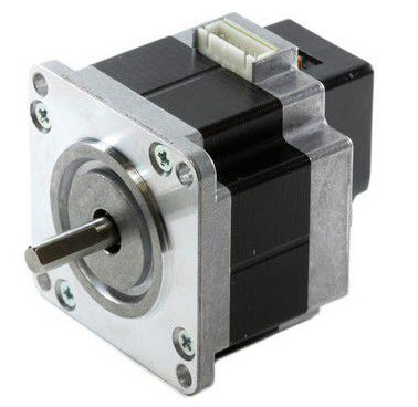
A stepper motor is a brushless electromechanical device that converts a series of electric pulses applied to its excitation windings into precisely defined, step-by-step mechanical shaft rotations. The motor’s shaft rotates through a fixed angle for each discrete pulse, with this rotation being either linear or angular. A single pulse input results in a one-step movement.
The angle through which the stepper motor shaft turns for each pulse is known as the step angle, typically expressed in degrees.
The number of input pulses given to the motor decides the step angle and hence the position of motor shaft is controlled by controlling the number of pulses. This unique feature makes the stepper motor to be well suitable for open-loop control system wherein the precise position of the shaft is maintained with exact number of pulses without using a feedback sensor.
If the step angle is smaller, the greater will be the number of steps per revolutions and higher will be the accuracy of the position obtained. The step angles can be as large as 90 degrees and as small as 0.72 degrees, however, the commonly used step angles are 1.8 degrees, 2.5 degrees, 7.5 degrees and 15 degrees.
The direction of the shaft rotation depends on the sequence of pulses applied to the stator. The speed of the shaft or the average motor speed is directly proportional to the frequency (the rate of input pulses) of input pulses being applied at excitation windings. Therefore, if the frequency is low, the stepper motor rotates in steps and for high frequency, it continuously rotates like a DC motor due to inertia.
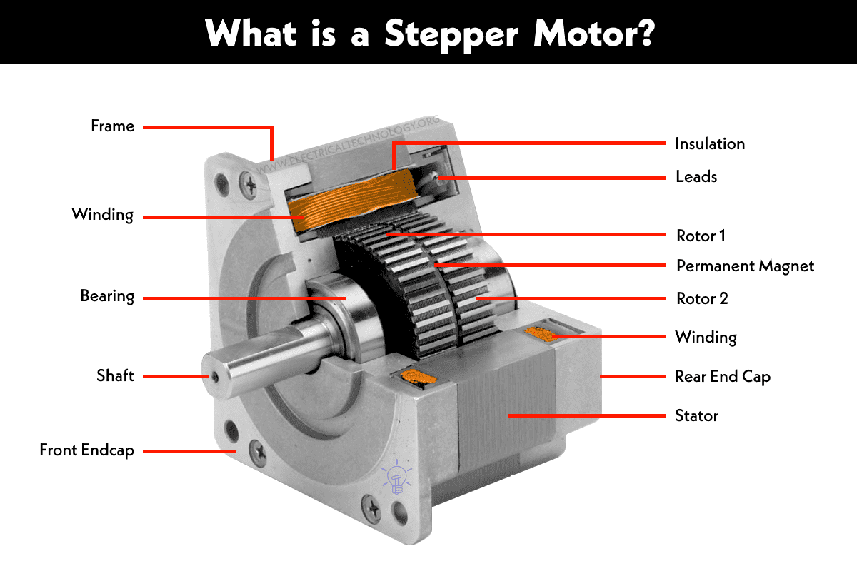
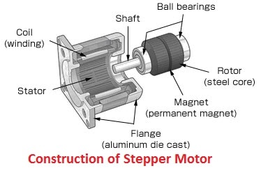
Construction of Stepper Motor
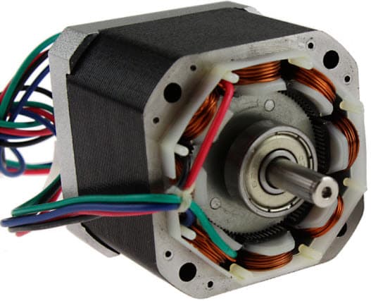
Like all electric motors, it has stator and rotor. The rotor is the movable part which has no windings, brushes and a commutator. Usually the rotors are either variable reluctance or permanent magnet kind. The stator is often constructed with multipole and multiphase windings, usually of three or four phase windings wound for a required number of poles decided by desired angular displacement per input pulse.
Unlike other motors it operates on a programmed discrete control pulses that are applied to the stator windings via an electronic drive. The rotation occurs due to the magnetic interaction between poles of sequentially energized stator winding and poles of the rotor.
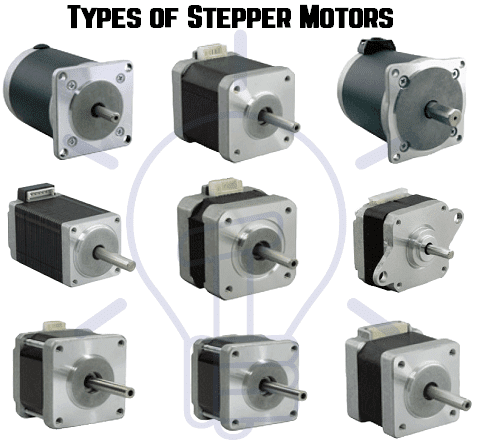
Today, the market offers several types of stepper motors across a wide range of sizes, step counts, constructions, wiring configurations, gearing options, and other electrical characteristics. Due to their ability to operate discretely, these motors are well-suited for interfacing with digital control devices such as computers.
Due to the precise control of speed, rotation, direction, and angular position, these are of particular interest in industrial process control systems, CNC machines, robotics, manufacturing automation systems, and instrumentation.
Types of Stepper Motors
There are three basic categories of stepper motors, namely
- Permanent Magnet Stepper Motor
- Variable Reluctance Stepper Motor
- Hybrid Stepper Motor
In all these motors excitation windings are employed in stator where the number of windings refer to the number of phases.
A DC voltage is applied as an excitation to the coils of windings and each winding terminal is connected to the source through a solid state switch. Depends on the type of stepper motor, its rotor design is constructed such as soft steel rotor with salient poles, cylindrical permanent magnet rotor and permanent magnet with soft steel teeth. Let us discuss these types in detail.
Variable Reluctance Stepper Motor
It is the basic type of stepper motor that has been in existence for a long time and it ensures easiest way to understand principle of operation from a structural point of view. As the name suggests, the angular position of the rotor depends on the reluctance of the magnetic circuit formed between the stator poles (teeth) and rotor teeth.
Construction of Variable Reluctance Stepper Motor
It consists of a wound stator and a soft iron multi-tooth rotor. The stator has a stack of silicon steel laminations on which stator windings are wound. Usually, it is wound for three phases which are distributed between the pole pairs.
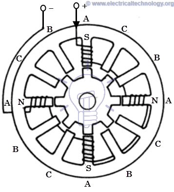
The number of poles on stator thus formed is equal to an even multiple of the number of phases for which windings are wounded on stator. In the figure below, the stator has 12 equally spaced projecting poles where each pole is wound with an exciting coil. These three phases are energized from of a DC source with the help of solid state switches.
The rotor carries no windings and is of salient pole type made entirely of slotted steel laminations. The rotor pole’s projected teeth have the same width as that of stator teeth. The number of poles on stator differs to that of rotor poles, which provides the ability to self start and bidirectional rotation of the motor.
The relation of rotor poles in terms of stator poles for a three phase stepper motor is given as, Nr = Ns ± (Ns / q). Here Ns = 12, and q= 3, and hence Nr = 12 ± (12 / 3) = 16 or 8. An 8-pole construction rotor without any excitation is illustrated below.
Working of Variable Reluctance Stepper Motor
The stepper motor works on the principle that the rotor aligns in a particular position with the teeth of the excitation pole in a magnetic circuit wherein minimum reluctance path exist. Whenever power is applied to the motor and by exciting a particular winding, it produces its magnetic field and develops its own magnetic poles.
Due to the residual magnetism in the rotor magnet poles, it will cause the rotor to move in such a position so as to achieve minimum reluctance position and hence one set of poles of rotor aligns with the energized set of poles of the stator. At this position, the axis of the stator magnetic field matches with the axis passing through any two magnetic poles of the rotor.
When the rotor aligns with stator poles, it has enough magnetic force to hold the shaft from moving to the next position, either in clockwise or counter clockwise direction.
Consider the schematic diagram of a 3-phase, 6 stator poles and 4 rotor teeth is shown in figure below. When the phase A-A’ is supplied with a DC supply by closing the switch -1, the winding become a magnet which results one tooth become North and other South. So the stator magnetic axis lies along these poles.
Due to the force of attraction, stator coil North Pole attracts nearest rotor tooth of opposite polarity, i.e., South and South Pole attract nearest rotor tooth of opposite polarity, i.e., North. The rotor then adjusts to its minimum reluctance position where the rotor magnetic axis exactly matches with stator magnetic axis.
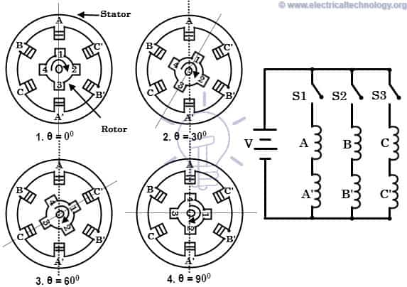
When the phase B-B’ is energized by closing switch -2 keeping phase A-A’ remain de-energized by opening switch-1, winding B-B’ will produce the magnetic flux and hence the stator magnetic axis shifts along the poles thus formed by it. Hence the rotor shifts to the least reluctance with magnetized stator teeth and rotates through an angle of 30 degrees in the clockwise direction.
When the switch-3 is energized after opening switch-2, the phase C-C’ is energized, the rotor teeth align with new position by moving through an additional angle of 30 degrees. By this way, the rotor moves clockwise or counterclockwise direction by successively exciting stator windings in a particular sequence. The step angle of this 3-phase 4-pole rotor teeth stepper motor is expressed as, 360/ (4 × 3) = 30 degrees (as step angle = 360 / Nr × q).
The step angle can be further reduced by increasing the number of poles on the stator and rotor, in such case motors are often wound with additional phase windings. This can also be achieved by a adopting different construction of stepper motors such as multistack arrangement and reduction gear mechanism.
Permanent Magnet Stepper Motor
The permanent magnet design motor is perhaps the most common among several types of stepper motors. As the name implies, it adds permanent magnets to the motor construction. This type of stepper motors is also referred as can-stack motor or tin-can motor. The main advantage of this motor is its low manufacturing cost. This type of motor has 48-24 steps per revolution.
Construction Permanent Magnet Stepper Motor
In this motor, the stator is of multipolar and its construction is similar to that of variable reluctance stepper motor as discussed above. It consists of slotted periphery on which stator coils are wound. It has projected poles on the slotted structure where the wound windings can be two or three or four-phase.
The end terminals of all these windings are bought out and connected to the DC excitation via solid state switches in the drive circuit.
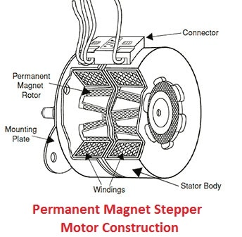
The rotor is made up of a permanent magnet material like a ferrite that can be in the shape of either cylindrical or salient pole, but usually it is of smooth cylindrical type. The rotor designed to have an even number of permanent magnetic poles with alternate North and South polarities.
Working of Permanent Magnet Stepper Motor
The operation of this motor works on the principle that unlike poles attract each other and like poles repel each other. When the stator windings are excited with a DC supply, it produces magnetic flux and establishes the North and South poles. Due to the force of attraction and repulsion between permanent magnet rotor poles and stator poles, the rotor starts moving up to the position for which pulses are given to the stator.
Consider a 2-phase stepper motor with two permanent magnetic rotor poles as shown in the figure below.
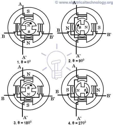
When the phase A is energized with a positive with respect to the A’, the windings establish North and South poles. Due to the force of attraction, the rotor poles align with stator poles such that the magnetic pole axis of rotor adjusts with that of stator as shown in figure.
When the excitation is switched to B phase and switching off phase A, the rotor further adjusts to magnetic axis of phase B, and thus rotates through 90 degrees in clockwise direction.
Next, if the phase A is energized with a negative current with respect to A’, the formation of stator poles causes the rotor to move through another 90 degrees in clockwise direction.
In the same way, if the phase B is excited with negative current by closing phase A switch, the rotor rotates through another 90 degrees in the same direction. Next, if the phase A is excited with positive current, the rotor comes to the original position thus making a 360 degrees complete revolution. This implies that, whenever the stator is excited, the rotor tends to rotate through 90 degrees in clockwise direction.
The step angle of this 2-phase 2-pole permanent magnet rotor motor is expressed as, 360/ (2 × 2) = 90 degrees. The step size can be reduced by energizing two phases simultaneously or a sequence of 1-phase ON and 2-phase ON modes with a proper polarity.
Hybrid Stepper Motor
It is the most popular type of stepper motor as it provides better performance than permanent magnet rotor in terms of step resolution, holding torque and speed. However, these motors are more expensive than PM stepper motors. It combines the best features of both variable reluctance and permanent magnet stepper motors. These motors are used in applications that require very small stepping angle such as 1.5, 1.8 and 2.5 degrees.
Construction of Hybrid Stepper Motor
The stator of this motor is same as its permanent magnet or reluctance type counterpart. The stator coils are wound on alternate poles. In this, the coils of different phases are wound on each pole, usually two coils at a pole which is referred as a bifilar connection.
The rotor consists of a permanent magnet which is magnetized in axial direction to create a pair of magnetic poles (N and S poles). Each pole is covered with uniformly spaced teeth. The teeth are made up of soft steel and two section, of which on each pole are misaligned each other by a half-tooth pitch.
Working of Hybrid Stepper Motor
This motor works similar to that of permanent magnet stepper motor. The figure above shows 2-phase, 4-pole, 6-tooth rotor hybrid stepper motor. When the phase A-A’ is excited with a DC supply, keeping B-B’ unexcited, the rotor aligns such that the south pole of the rotor faces north pole of the stator while north pole of rotor faces south pole of the stator.
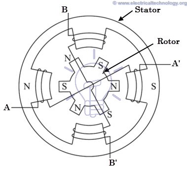
Now, if the phase B-B’ is excited, keeping A-A’ switched off in such a way that upper pole becomes north and lower becomes south, then the rotor will align to a new position by moving through counterclockwise direction. If the phase B-B’ is oppositely excited such that the upper pole becomes south and lower becomes north, then the rotor will turn clockwise direction.
By a proper sequence of pulses to the stator, the motor will turn in desired direction. For every excitation, rotor will get locked into new position, and even if excitation is removed motor still maintains its locked condition due to the permanent magnet excitation. The step angle of this 2-phase, 4-pole, 6-tooth rotor motor is given as 360/ (2 × 6) = 30 degrees. In practice, hybrid motors are constructed with more number of rotor poles in order to get high angular resolution.
- Related Post: Motor Efficiency and How to improve it?
Unipolar and Bipolar Stepper Motors
The above discussed motors can be unipolar or bipolar based on the coil winding arrangements. A unipolar motor is employed with two windings per phase and hence the direction of current flow through these windings changes the rotation of the motor. In this configuration, the current flow is through one direction in one coil and opposite direction in another coil.
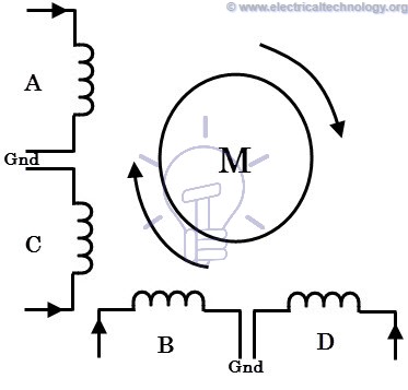
The figure below shows 2-phase unipolar stepper motor wherein A and C coils are for one phase and B and D are for other phase. In each phase each coil carries current in opposite direction to that of other coil. Only one coil will be carrying current at a time in each phase for achieving particular direction of rotation. So just by switching the terminals to each coil, the direction of rotation is controlled.
In case of a bipolar stepper motor, each phase consists of a single winding rather than two in case of unipolar one. In this, the direction of rotation is controlled by reversing the current through the windings. Hence, it requires a complex drive circuit for current reversal.

- Related Post: Cable Size Calculation for LT & HT Motors
Stepping Modes of a Stepper Motor
A typical stepping action causes the motor to step through a sequence of equilibrium positions in response to current pulses given to it. It is possible to vary the stepping action in different ways simply by changing the sequence through which stator windings are energized. The following are the most common operating or driving modes of stepper motors.
- Wave step
- Full step
- Half step
- Microstepping


Wave Step Mode
Wave step mode is the simplest of all other modes in which only one winding is energized at any given time. Each coil of the phase is connected to the supply alternatively. The table below shows the order through which coils are energized in a 4-phase stepper motor.
In this mode motor gives maximum step angle compared to all other modes. It is the simplest and most commonly used mode for stepping; however the torque produced is less as it uses some part of the total winding at a given time.
Full Step Mode
In this drive or mode, two stator phases are energized simultaneously at any given time. When two phases are energized together, the rotor will experience the torque from both phases and comes to the equilibrium position, which will be interleaved between two adjacent wave step positions or 1-phase excitations. So this step provides better holding torque than wave step. The table below shows the full step drive for 4-phase stepper motor.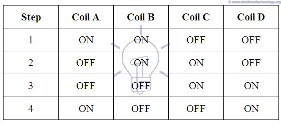
Half Step Mode
It is the combination of both wave and full step modes. In this, single phase and dual phase excitations are carried out alternatively, i.e., one-phase ON, two-phases ON, and so on. The step angle in this mode becomes half of the full step angle. This drive mode has highest torque and stability compared to all other modes. The table containing phase pulsing sequence for a 4-phase motor in half stepping is given below.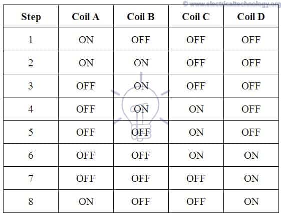
Microstepping Mode
In microstepping mode, each motor step is subdivided into several small steps, sometimes even hundreds of fixed positions, resulting in a greater positioning resolution. In this mode, the currents through the windings are continually varied to achieve very small steps. Two phases are excited simultaneously in this configuration, but with unequal currents in each phase.
For example, the current through phase -1 is held constant while the current through phase-2 is incremented in steps till the maximum value of current, whether it is negative or positive. The current in the phase-1 is then decreased or increased in steps till zero. Thus, the motor will produce a small step size.
All these stepping modes can be obtained by each type of stepper motor discussed above. However, the direction of current in each winding during these steps can be varied depending on the type of motor and either it is unipolar or bipolar.
Advantages & Disadvantages of Stepper Motors
Advantages:
- At standstill position, the motor has full torque. No matter if there is no moment or changing position.
- It has a good response to starting, stopping and reversing position.
- As there is no contact brushes in the stepper motor, It is reliable and the life expectancy depends on the bearings of the motor.
- The motor rotation angle is directly proportional to the input signals.
- It is simple and less costly to control as motor provides open loop control when responding to the digital input signals.
- The motor speed is directly proportional to the input pulses frequency, this way a wide range of rotational speed can be achieved.
- When load is coupled to the shaft, it is still possible to realize the synchronous rotation with low speed.
- The exact positioning and repeatability of movement is good as it has a 3-5% accuracy of a step where the error is non cumulative from one step to another.
- Stepper motors are safer and low cost (as compared to servo motors), having high torque at low speeds, high reliability with simple construction which operates at any environment.
Disadvantages
- Stepper motors having low Efficiency.
- It has low Accuracy.
- Its torque declines very quickly with speed.
- As stepper motor operates in open loop control, there is no feedback to indicate potential missed steps.
- It has low torque to inertia ratio means it can’t accelerate the load very quickly.
- They are noisy.
Applications of Stepper Motors
Stepper motors are used in a wide range of applications due to their precise control over movement and ability to maintain position without feedback. Some common applications include:
- Automation: Stepper motors are used in automated production equipment, automotive gauges, and industrial machines like packaging, labeling, filling, and cutting, etc.
- 3D Printing: Stepper motors are commonly used in 3D printers to control the movement of the print head and build platform, allowing for precise control over the printing process.
- CNC Machines: Computer Numerical Control (CNC) machines use stepper motors to control the movement of cutting tools and other components, allowing for precise and repeatable machining operations.
- Robotics: Stepper motors are widely used in robotics for controlling the movement of robot arms, legs, and other components, providing precise control over the robot’s motion.
- Automotive: Stepper motors are used in automotive applications for controlling various systems, such as fuel injection, idle speed control, and headlight positioning.
- Medical Devices: Stepper motors are used in various medical devices, such as samples, respirators, fluid pumps, blood analysis machinery, medical scanners, fluid and infusion pumps, and medical imaging equipment, for precise control over movement and positioning.
- Textile Machinery: Stepper motors are used in textile machinery for controlling the movement of the fabric, yarn, and other components, allowing for precise control over the manufacturing process.
- Security and Camera Systems: Stepper motors are used in security devices such as security and surveillance cameras systems for controlling the movement of lenses and other components, allowing for automatic zoom, precise focusing and positioning.
- Consumer Electronics: Stepper motors are used in consumer electronics, such as printers, image scanners, photocopiers, digital cameras and disk drives, for controlling the movement of components and devices.
- Heavy Load Applications: Stepper motors are also used in elevators, conveyor belts, and lane diverters.
These are just a few examples, and the use of stepper motors continues to expand as new applications are developed.
Related Posts:
- What is a Linear Induction Motor – Working Principle and Applications
- Difference Between Single Phase & Three Phase Induction Motor
- Why Motor rated in kW instead of kVA?
- What is Motor Generator Set and How Does it Work?
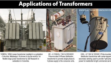
- Electrical Transformer – Construction, Working, Types and Applications
- Alternator or Synchronous Generator: Construction, Working, Types & Applications
- Induction Generator or Asynchronous Generator: Construction & Working
- Speed Control of DC Motor – Voltage, Rheostatic & Flux Control Methods
- AC Drive – Working and Types of Electrical Drives & VFD
- DC Drive – Working and Types of DC Drives
- Three Phase Motor Power & Control Wiring Diagrams
- Electric Motors Symbols
- Applications of Electric Motors


VERY NICE NOTES
can you explain about solid state relay
Hi Alif,
You may refer to the article: Solid State Relay: Types of SSR Relays – Construction and Operation
Hello,
can I use your picture: Working of Hybrid Stepper Motor for my thesis.
Kind regards.
Žan
Hi Zan, yes, you can. Please add a reference link back to the original work. Thanks.
I’d like to use variable reluctance stepper motors in a hobby project. Specifically a very simple 4/2 pole configuration. Any tips on where these can be purchased online?