What is DC Drive? Operation and Classification of DC Drives
What are DC Drives? Analog and Digital DC Drives
DC drive technology is efficient, reliable, cost effective, operator friendly and relatively easy to implement. DC drive provides many advantages over AC drives, especially for regenerative and high power applications. DC drives have been widely used in industrial drive applications in order to offer very precise control.
Of course, Variable Frequency Drives (VFDs) and AC motors are now offering an alternative to DC drives and motors, but there are many other applications where DC drives are extensively used including crane and hoists, elevators, spindle drives, winders, paper production machines, crushers, etc. due to the advantages of DC drives.
What are DC Drives?
DC drive is basically a DC motor speed control system that supplies the voltage to the motor to operate at desired speed. Earlier, the variable DC voltage for the speed control of an industrial DC motor was generated by a DC generator.
By using an induction motor, the DC generator was driven at a fixed speed and by varying the field of the generator, variable voltage was generated. Soon after this Ward Leonard set was replaced by a mercury arc rectifier and later by thyristor converters. Nowadays, the thyristor family of devices is used widely to control the speed of the DC motor.
Components of a DC Drive?
The main components of a DC drive system are shown in figure below.
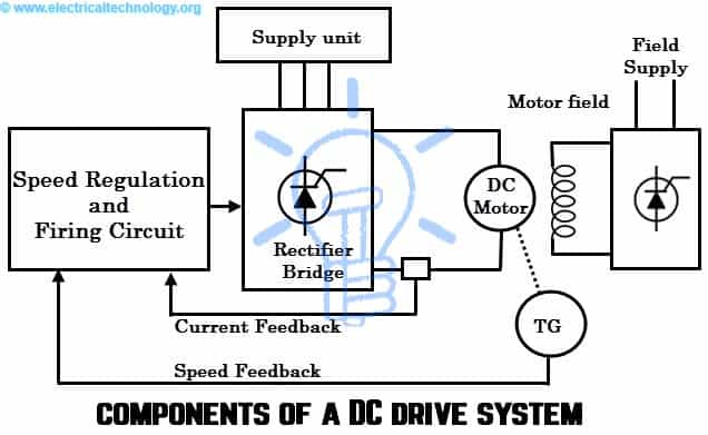
DC Drive Input: Some thyristor based DC drives operate on a single phase supply and use four thyristors for full wave rectification. For larger motors, three phase power supply is needed because the waveforms are much smoother. In such cases, six thyristors are needed for full wave rectification.
Rectifier Bridge: The power component of a controlled DC drive is a full wave bridge rectifier which can be driven by three phase or single phase supply. As mentioned above the number of thyristor may vary depends on the supply voltage.
A six-thyristor bridge (in case of three phase converter) rectifies the incoming AC supply to DC supply to the motor armature. The firing angle control of these thyristors varies the voltage to the motor.
Field Supply Unit: The power to be applied to the field winding is much lower than the armature power, so, most often single phase supply is provided. A separate thyristor bridge or diode rectifier is used for supplying the power to the field winding of the motor.
In many cases a two-phase supply is drawn from the three phase input (that supplies power to the armature) and hence the field exciter is included in the armature supply unit.
The function of the field supply unit is to provide a constant voltage to the field winding to create a constant field or flux in the motor. In some cases, this unit is supplied with thyristors to reduce the voltage applied to the field so as to control the speed of the motor above the base speed.
In case of permanent magnet DC motors, the field supply unit is not included in the drive.
Speed Regulation unit: It compares the operator instruction (desired speed) with feedback signals and sends appropriate signals to the firing circuit. In analog drives, this regulator unit consists of both voltage and current regulators. The voltage regulator accepts the speed error as input and produces the voltage output which is then applied to the current regulator.
The current regulator then produces required firing current to the firing circuit. If more speed is required, additional current is called from the voltage regulator and hence thyristors conducts for more periods. Generally, this regulation (both voltage and current) is accomplished with proportional-integral-derivative controllers.
The field current regulator is also provided where speed greater than the base speed is required.
In modern digital microprocessor based drives, the speed control is achieved with a lookup table to determine the current for the firing circuit with additional digital circuitry.
Firing Circuit: It supplies the gate pulses to thyristors so that they turned ON for particular periods to produce variable armature voltage. Isolation is also provided in this gate drive circuit.
Working Principle of DC Drives
In DC motors, the speed is proportional to the armature voltage and inversely proportional to the field current. And also, the armature current is proportional to the motor torque. Therefore, by increasing or reducing the applied voltage, the speed of the motor is varied. However, it is possible up to the rated voltage. If the speed greater than the base speed is required, the field current of the motor has to be reduced.
By reducing the field current, the flux in the motor reduces. The reduction of field current reduces the armature counter emf. The more armature current flows if there is less counter armature emf. Further, this armature current increases the motor torque and hence the speed. These are the two basic principles employed in DC drives to control the speed of the motor.
In armature controlled DC drives, drive unit provides a rated current and torque at any speed between zero and the base of the motor. By varying the armature voltage, variable speed is obtained as shown in figure.
Generally, a fixed field supply is provided in these DC drives. As the torque is constant (which describes a load type) over the speed range, the motor output horsepower is proportional to the speed (HP = T × N / 525). The motor characteristics of this drive are shown below.

In case of armature and field controlled drives, the armature voltage to the motor is controlled for constant torque-variable HP operation up to the base speed of the motor. And for the above base speed operation, drive switches to the field control for constant HP- reduced torque operation up to maximum speed as shown in figure below. In this case, reducing the field current increases the speed of the motor up to its maximum speed as shown in figure.

Digital and Analog DC Drives

Nowadays, digital implementations have replaced analog circuitry of electric drive system in all forms of industrial control. Digital controllers offer greater flexibility to produce the precise control, self-tuning, and ease of interfacing with host computers and other drives. However, a basic understanding of analogue version DC drive makes less difficult to understand its digital equivalent. Let us look on both of these DC drives.
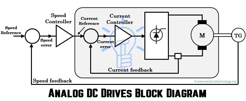
Analog DC Drives
A standard analog DC drive with speed and current control is shown in figure below. The objective of this system is to provide speed control and hence the speed reference becomes the input to the system and speed of the motor is the output of the system which is measured by the tachometer.
The working of this drive goes like this; consider that motor is running at a set speed. Now, the speed reference signal has increased to somewhat greater than the actual speed. So there will be an error speed signal at left-hand summing junction as shown in figure. This speed error indicates the required acceleration by the motor, which means the torque and hence more current.
The error is amplified by the speed controller (which is basically a speed-error amplifier) and its output is given as current input reference to the inner control system. As the current reference increases, the inner current controller drives the more current to the motor thereby extra torque is provided.
The inner current loop is responsible for maintaining the zero current error between the actual motor current and current reference signal which means to make actual motor current to follow the reference current. The amplified current error signal from the current controller controls the firing angle of the bridge and hence the output voltage of the converter. The current feedback is achieved either by DC transformer or by AC transformer (with rectifier) in the main supply lines.
This entire operation is performed by a current error amplifier with a high gain. In most cases, this amplifier is of proportional plus integral control (PI) type circuit that maintains the actual and desired currents exactly equal under steady-state conditions. This current controller also limits the current through the motor by considering the minimum and maximum currents of the motor.
The outer loop provides the speed control by comparing the actual speed obtained by the DC tachogenerator with desired or required speed from the speed reference. These two inputs are fed into the speed-error amplifier, and then resulted error is amplified and applied as an input to the current controller.
The speed amplifier produces the current output proportion to the speed error. For this amplifier also a PI control is employed (by using analog electronics) in order to achieve zero steady state error. Using this, the actual speed of the motor is maintained exactly at reference speed for all loads.
Digital DC Drives
With the advancements in digital control, DC drives become more flexible and faster (due to faster response times) compared with analog drives. A schematic arrangement of digital DC drive is shown in below figure; of course it is similar to the analog scheme, but here analog circuit (analog amplifiers) is replaced by digital circuitry.
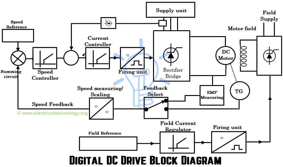
A speed reference signal given as the drive’s input compared with the feedback speed in the summing circuit. If the output of the summing circuit is positive error, indicating that a speed increase is required and if it generates a negative error, indicating that a speed decrease is required (because motor is operating at faster than desired speed).
The error speed is given to the speed controller in the microprocessor which determines output voltage to operate the motor at desired speed. At the same time, current controller in the microprocessor determines the firing signals to the SCRs in the bridge converter. SCRs then convert the three phase supply to DC supply in relation to the desired speed.
This drive can operate in open loop without any feedback and can achieve a speed regulation of 5-8%. However, a speed regulation less than 5% is required in many applications. In such cases, the speed measuring/scaling unit switches to the EMF feedback measuring circuit.
This feedback circuit measures the armature voltage, scales it in proportion to the output voltage (scaling function in microprocessor) and gives to the summing circuit. Further, it is transformed into a speed error signal in speed controller.
If the speed regulation less than 1% is required, tachometer generator feedback is used. So the speed measuring/scaling circuit then switches to the tachometer feedback. This feedback achieves very precise control compared with EMF feedback.
Also for field control (above rated speeds), this drive includes a separate field exciter. A field current regulator in the microprocessor determines the voltage to the field windings by accepting the flux/field reference signal from the operator. This regulator provides the firing signals required by the field converter unit to produce the required DC voltage proportional to the speed.
What’s inside of Power Conversion make SCR DC Drives?
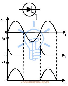
Silicon Controlled Rectifiers (SCRs) are widely used thyristors for large DC motor drives in its power conversion unit. An SCR conducts when a small voltage applied to its gate terminal. Its conduction continues till the starting of negative cycle and it turned OFF automatically once the voltage across the SCR goes through natural zero till next gated signal.
The purpose of using these SCRs in DC drives is to convert the fixed AC supply to variable DC supply that controls the motor speed.
As discussed earlier, some SCR DC drives are supplied from single phase AC supply and use four SCRs in the form of bridge for the DC rectification. In case of high power DC drives, a three phase supply with six SCRs is used for DC rectification.
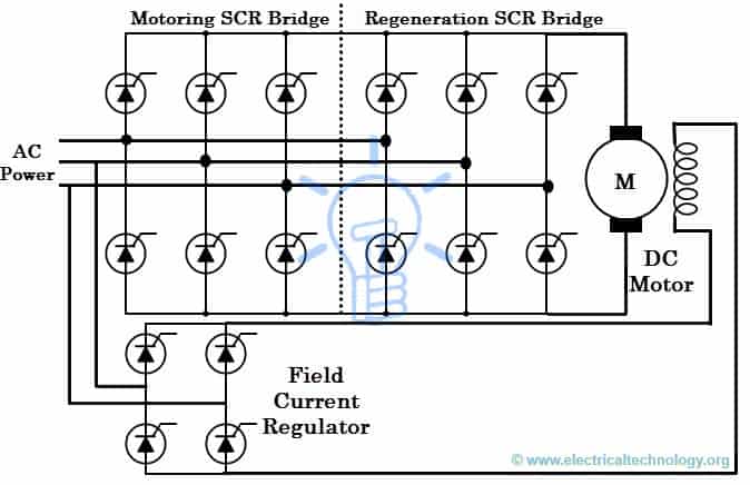
In case four quadrant operation (forward motoring, forward braking, reverse motoring and reverse braking) of the DC drive, a bridge rectifier of consisting of 12 SCRs with a three phase incoming supply is used. During each quadrant operation, SCRs are triggered at a phase angle in order to provide required DC voltage to the motor.
The connection of SCRs (for four quadrant operation of the drive) from incoming three phase AC supply to the DC output is shown in figure below. In this, the motoring SCR bridge and regeneration SCR bridge achieve the drive four quadrant operation by receiving the appropriate gate signals from (analog or digital) controller.
If the SCRs were gated with a phase angle of zero degrees, then the drive function as a rectifier which feds the full rectified rated DC supply to the motor and by varying the firing angle to the SCRs, a variable DC supply is applied to the motor.
The DC output voltage waveform in relation to the AC waveform for above circuit is shown below. This average DC output voltage is obtained for 400, 320 and 240 firing phase angles. By this way, the average output is controlled by varying the firing phase angles to the SCRs.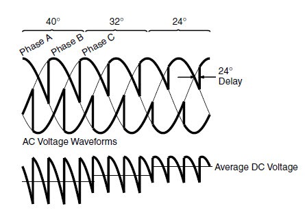
As the field winding also requires the regulated DC supply, only four SCRs are used in the field bridge converter. This is because field never requires a negative current and hence another set of SCRs is not required, which were used in armature for reversing the motor.
In modern DC drives, SCRs are completely replaced by MOSFETs and IGBTs in order to achieve high speed switching so that distortion to the AC incoming power and currents during switching is eliminated. Hence, the drive becomes more efficient and accurate.
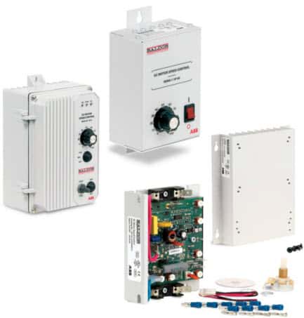
As discussed in AC drives article, DC drives are also available in modular units that consisting analog and digital I/Os, multifunctional keypads, remote operator panels in addition to the software programming and configuring capabilities, from various manufacturers such as ABB, Siemens, Rockwell automation, Emerson, etc. These can be connected to the other drives or a computer host via communication cables.

Programming macros of these drives enables to implement any control structure to an application. These are also capable of receiving the remote control signals from remote programmable logic controllers via field bus communication systems.
Related Posts:
- Design & Installation of Control & Monitoring Systems in Electrical Engineering
- Metering, Energy Metering, Monitoring & Measurement Transducers
- Failures In Electrical Systems, Equipment & Materials
- What Exactly Is A Smart Grid? Smart Grid Applications
- Integration of Renewable Energy with Grid System
- What is Soft Starter? Its Working, Diagram and Applications
- Star Delta Starter – (Y-Δ) Starter Power, Control and Wiring Connection
- STAR-DELTA Starter Motor Starting Method Without Timer
- Direct Online Starter – DOL Starter Wiring Diagram for Motors
- What is Motor Starter? Types of Motor Starters and Motor Starting Methods
- Motor Protection – Types of Faults and Protection Devices
- Types of Electric Motors – Classification of AC, DC & Special Motors
- What is a Contactor ? Types, Working and Applications
- Why Do We Need to Install a Starter with a Motor?
- Single-Phase Induction Motor – Construction, Working, Types & Applications
- Three-Phase Induction Motor – Construction, Working, Types & Applications
- What Exactly Is A Smart Grid? Smart Grid Applications
- Integration of Renewable Energy with Grid System
- What are Industrial Communication Networks? An Overview


GRACIAS POR DEJARME,SABER DE USTEDES..ESTOY MUY CONTENTO DE HABERLOS ENCONTRADO..FELICITARLOS POR SU MUY COMPLETA Y MAGNIFICA PAGINA…MUY BUEN ESFUERZO EL DE TODOS USTEDES…..LOS SEGUIRE SIEMPRE…..GRACIAS OTRA VEZ,DESDE COLOMBIA…..
I like this but ,I want practically wiring of all meters & control wiring .
What happens when the shunt field of a compound wound motor is left on whilst not running, will this cause the shunt fields to burn
The Field windings will definitely burn out if left energized without adequate cooling air provided at your motor. It is a non issue to have an energized field if cooling air is provided. Many systems have incorporated interlocks in the cooling air via pressure switches, sail switches etc that will kill the drives if adequate flow, and pressure are not achieved. That being said, I have seen this type of system fail as sail switches are notorious for sticking on even in the event of no flow. A redundant system works best in these scenarios especially if your motors are fed from a common cooling air supply.
Thank for you this article, very insightful overview!
Hello, good evening, from Colombia
Could you please help me with the Electronic Diagrams, the Drivers, for the variators of speed, of CCY where I could get all their parts? Thank you very much, greetings from Colombia, do not know how much I appreciate and value, all this knowledge, what we share
can i know the advantages and disadvantsages of DC motor drive and AC motor drive
Great post!