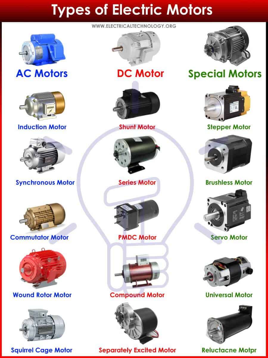
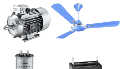
Classification of Different Types of Electrical Motors
An Electrical Motor is a machine that converts electrical energy into mechanical energy. It is used for generating torque to lift loads, move objects & various other mechanical work. In the following article, we will discuss the different types of electric motors such as AC, DC and special types of motors etc.
An electrical motor is mainly classified into three types.
- AC Motors
- DC Motors
- Special Motors
AC Motor
The AC electric motor converts AC (Alternating Current) electrical energy into mechanical energy. These electric motors are powered using a single-phase or three-phase alternating current. The basic working principle of AC motor is the rotating magnetic field (RMF) generated by the stator winding when an alternating current is passed through it. The rotor (having its own magnetic field) follows the RMF & starts rotation.
The AC motors are further classified into two types.
- Synchronous Motor
- Asynchronous or Induction Motor
Synchronous Motor
As its name suggests, such AC motor has a constant speed called synchronous speed that only depends on the frequency of the supply current. The speed of such electric motors only varies with variation in supply frequency & remains constant upon varying loads. It is used for constant speed application & precision control.
A synchronous motor has the same stator design as asynchronous motor & it generates a rotating magnetic field when supplied with input alternating current. While the rotor design may vary i.e. it uses a separate DC excitation to generate its own magnetic field.
- Related Post: Difference between Synchronous and Asynchronous Motor
Excited Synchronous Motor
Such synchronous motor requires DC excitation. The DC excitation means that the rotor has a separate DC supply to generate its own magnetic flux. This flux reacts with the revolving flux of the stator to generate rotation. The utilize wire wound rotor with commutator & brushes assembly to supply current to the rotor’s windings.
Single Phase Synchronous Motor
Such synchronous motor runs on single-phase AC supply. To be precise, it actually uses two-phase, the second one being derived from the first phase. The reason for using two phases is that a single phase cannot generate a rotating magnetic field. Such motor can start in either direction i.e. its direction is unidentified, which is why there is an extra starting arrangement used for giving it a direction.
The speed of such a motor only depends on the supply frequency. They are used in recording instruments, electric wall clocks.
Three Phase Synchronous Motor
These synchronous motor runs on three-phase power supply. The benefit of a three-phase alternating current is that it generates a rotating magnetic field in the stator while the arrangement of the phases decides the direction of the rotation. These motor does not need any special starting mechanism to decide its direction. However, the rotor still needs an extra DC source for excitation.
They are used in industries for applications that require constant speed over a range of loads & require precise positioning in robotics.
Unexcited Synchronous Motor
Such synchronous motor that does not require DC excitation i.e. the rotor does not require separate DC supply for generating magnetic flux. They utilize squirrel cage rotors such as the one used in induction motor.
Reluctance Motor
It is a single-phase synchronous motor that works on the principle of generating torque based on the magnetic reluctance. There are two types of stator windings i.e. main windings & auxiliary windings. The auxiliary windings in used for starting the motor. It has a squirrel cage type rotor (with no windings) just like in an induction motor made of ferromagnetic material.
The motor starts like an actual single phase induction motor using the auxiliary winding. Once the motor reach near synchronous speed, the auxiliary winding is disconnected & the rotor is locked in synchronism due to the rotor’s ferromagnetic nature trying to keeping itself in the less reluctance position inside the rotating magnetic field.
Related Posts:
- Why We Need to Install a Starter with a Motor?
- What is Motor Starter? Types of Motor Starters and Motor Starting Methods
Hysteresis Motor
Such type of synchronous motor works on the principle of hysteresis loss or residual magnetism occurring in the rotor. Such electric motors are operated using single-phase as well as three-phase AC supply. in a single-phase hysteresis motor, there is an auxiliary winding beside the main winding as in a reluctance motor. The rotor which is in a cylindrical shape is made of ferromagnetic material with high magnetic retentivity or hysteresis loss such as hardened steel. The rotor is supported by a non-magnetic shaft.
The motor starts as an induction motor. The stator’s rotating magnetic field induces eddy current in the rotor. The eddy current generates torque along with the hysteresis torque due to the high hysteresis loss property of the rotor’s material. Due to the eddy current torque, the motor behaves as an induction motor.
Once the motor reaches the near synchronous speed, the stator’s rotating magnetic field pulls the rotor in synchronism. The rotor ferromagnetic nature produces opposite magnetic poles due to the stator’s RMF & it starts behaving as a permanent magnet. At such speed, there is no relative motion between stator & rotor. So there is no induction. Therefore, there is no eddy current or eddy current torque. The torque produced by the motor in synchronous speed in due to hysteresis which is why it is named Hysteresis motor.
The main advantage of a hysteresis motor is that it is brushless & there are no windings inside the rotor. It does not generate any noise & it operates quietly.
Disadvantages
- It generates very low torque
- If the load torque increases a certain limit, its speed drops thus it no longer operate as synchronous motor
- It has less efficiency
- It is only available in small sizes.
It is used in record players that require constant speed for recording & playback features. Also electric clock requires constant speed etc.
Asynchronous Motor
The type of AC motor that never runs at synchronous speed is called asynchronous speed. Its rotor speed is always less than the synchronous speed. It does not require separate rotor excitation.
The asynchronous motors are briefly classified into two types;
- Induction Motor
- Commutator Motor
Induction Motor
The induction motor is a type of AC asynchronous motor that works on the principle of electromagnetic induction between the stator & the rotor. The revolving magnetic flux induces a current in the rotor due to electromagnetic induction which produces torque in the rotor. It is the most used electrical motor in industries.
It is mainly divided into two types based on the construction of its rotor.
Related Posts:
- Single-Phase Induction Motor – Construction, Working, Types & Applications
- Three-Phase Induction Motor – Construction, Working, Types & Applications
Squirrel Cage Induction Motor
The rotor of such an induction motor resembles a squirrel cage. It is made from copper bars connected at both ends using a conductive ring to make a closed-loop circuit. There is no electrical connection to the rotor.
The stator’s varying magnetic field induces a current in the rotor’s bars. The induced current generates its own magnetic field in the rotor which interacts with the stator’s revolving magnetic field & tries to eliminate it by revolving with it in the same direction.
It has a simple design, inexpensive & it is more reliable. Since there are no electrical connection or commutator & brush assembly, it requires less maintenance.
Slip Ring or Wound Rotor Induction Motor
A slip ring or wound rotor induction motor is another type of induction motor where the rotor is made of windings that are connected with the slip rings. The slip rings are used to connect the windings to external resistors for controlling the rotor current & hence allowing the control of speed/torque characteristics.
It has the same operation principle as squirrel cage induction motor except for the induced current in the rotor can be controlled using the external resistors. The external resistance also helps to increase the rotor resistance during the startup of the motor to reduce the high inrush current. It also increases the starting torque to left high inertia loads.
The downside of slip rings is that it constantly slides with the brushes that require costly maintenance due to mechanical wear & tear. The construction is complex & it is more expensive than a squirrel cage motor.
Capacitor Start Induction Run Motor
It is a single-phase induction motor that utilizes a capacitor in series with its auxiliary winding to generate extra torque during its startup. Its name clearly suggests that the capacitor is only used for starting the motor & it is disconnected once the motor reaches near synchronous speed using a centrifugal switch.

It has two stator windings called main windings & auxiliary winding. The auxiliary winding is connected in series with the capacitor using a centrifugal switch. When the motor starts, the current flows through both windings generating high starting torque. Once the motor reaches 70-80% full speed, the centrifugal switch disconnected the supply to the auxiliary windings. The motor resume operating on the main winding.
Capacitor Start and Capacitor Run Motor
It is also a single-phase induction motor but it utilizes two capacitors in its operation. The two capacitors are the start capacitor & run capacitor. The start capacitor is used for only starting the capacitor to offer extra high starting torque while the run capacitor is used continuously for normal operation to run the motor. The starting capacitor is connected & disconnected using a centrifugal switch.

When the motor starts, both capacitors are connected offering high starting torque to the rotor. As the rotor’s speed pickup, the switch disconnects the starting capacitor. Such motor uses both main & auxiliary winding continuously which is why its operation is smoother than the motor running on main windings only such as capacitor run motors.
Related Post: What is the Role of Capacitor in a Ceiling Fan Motors?
Commutator Motor
This is a type of AC motor that utilizes commutator & brush assembly to supply power to its rotor. Such electric motors have wound-type rotor.
AC Series Motor
As we know, electric motors have two types of windings i.e. the stator windings known as the field windings & the rotor windings or armature windings.
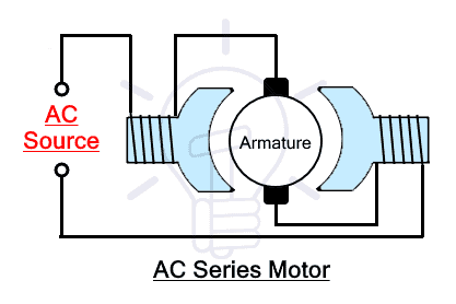
When these both windings are connected in series it is known as series wound motor. It is also known as universal motor due to its capability to run on both AC & DC supply as well.
The field windings carry the same amount of current as the rotor windings. The brushes that supply current to the armature winding through the commutator shorts the armature windings & acts as a shorted transformer. The brushes generate arcs that decrease with the increase in speed.
AC Compensated Series Motor
It is a modified form of AC series motor where an additional winding known as compensating winding is added in series with the existing field & armature windings to eliminate the transformer effect that happens in an uncompensated series motor.

The compensating winding is added in the stator besides the field windings & it is connected as shown in the figure to eliminate or mitigate the arcing problem.
Related Posts:
- Types of Inductors and Their Applications
- Fuse and Types of Fuses – Construction, Operation & Applications
Repulsion Motor
Repulsion motor is also an AC single phase motor where the AC input is only applied to the field or stator windings. The armature windings are connected to the commutator. The armature windings are shorted by using a pair of shorted brushes. There is no electrical connection between the field windings & armature windings. The rotor current is generated through induction.

The brushes are configured in such a way that it can be moved to change its angle with respect to an imaginary stator axis. The motor can be stopped, start & reversed by changing the angle of the brushes & also vary the speed of the motor.
As the rotor is shorted using the brushes to form a loop, a current is induced when alternating current flows in the field winding. This induced current flowing in the rotor’s windings generates its own magnetic field. The direction of the magnetic field depends on the brushes angle. This magnetic field interacts with the stator’s field & rotor reacts accordingly. For rotation, the brushes are slightly rotated at 20° at either direction to rotate the motor in that direction. Placing the brushes at 90° or 180° or 0° would stop the motor. Varying the angle increases or decrease the repulsion between the stator & rotor’s magnetic field & the rotor’s speed varies.
The starting torque can also be controlled by varying the angle of brushes providing maximum starting torque at 45°. This motor was used for traction due to its superior speed regulation but it has been superseded by other traction motors.
Related Posts:
Repulsion-Start Induction-Run Motor
Repulsion Induction motor or also known as repulsion-start induction-run motor is a modified version of squirrel cage induction motor that uses the high starting torque feature of repulsion motor & normally run as a squirrel cage induction motor.
There is a special mechanism for starting & running the motor. During the motor startup, a pair of shorted brushes is connected with the commutator in an angle such as in the repulsion motor. Once the motor picks up its speed, the mechanism lifts the brushes & connects the bar together by shorting the commutator to form a squirrel cage rotor. The motor resumes operation as an induction motor.
The benefit of the repulsion start offers 5-6 times high starting torque as compared to any other induction motor. The brushes also have a longer life span as it is only used for starting of the motor. Therefore, these electric motors have high mechanical life & require less maintenance.
DC Motor
The DC motor is another main type of electrical motor that only runs on DC or Direct Current. There are no phases in direct current that is why DC electric motors only uses 2 wires to run. They are the first motors to be invented. It is easier to control its speed by only varying the supply voltage. It offers simple starting, stopping, accelerating & reversing mechanisms. The installation cost of DC motor is very cheap but they do require maintenance whose cost increases significantly with increasing the size & power of the motor.
- Related Post: Difference Between AC and DC Motors
The basic working principle of DC motors is the Fleming’s left hand rule. A current carrying conductor inside a magnetic field experience a force of thrust mutually perpendicular to each other.
The DC motors can be briefly classified into following types
- Brushed DC Motor
- Brushless DC Motor
- Coreless or Ironless DC Motors
Brushed DC Motor
As the name suggests, such DC electric motors have brushes & commutators. They are used for connecting a stationary circuit with a rotating circuit. In such case, the rotor winding of the motor is energized through conductive brushes. The disadvantage of any brushed motor is that they require frequent maintenance due to continuous sliding of brushes & the sparks generated between them. However, they are quite simple in design & are in expensive.

The brushed DC electric motors are further classified into
- Separately Excited Motor
- Self-Excited DC Motor
- Permanent Magnet DC Motor
Separately Excited DC Motor
Such type of DC motors has separate excitation. The excitation refers to the energizing of the field windings also known as the stator’s windings. Both windings i.e. field windings & armature’s windings are connected with a separate power supply.

In such configuration, we can independently strengthen the magnetic field by increasing the DC excitation without changing the armature current. This is the main distinguishing point that the armature current does not flow through the field winding.
Self-Excited DC Motor
Such type of brushed DC motors has self-exciting field windings. The field winding is electrically connected with the armature windings. A single power source energizes both windings. Therefore, it does not require separate excitation source.
However, the field windings can be connected in series, parallel & partly series configuration with the armature windings. This is why self-excited DC motors are further classified into following types.
- Series Wound
- Shunt Wound
- Compound Wound
Series Wound DC Motor
In a series wound DC motor, the field winding is connected in series with the armature windings. Therefore the current flowing through the field windings is same as the current flowing through the armature windings.

The speed of such electric motors varies with varying the load connected to the motor.
Shunt Wound DC Motor
Such DC motors have the field winding (also known as shunt field winding) connected in parallel with the armature winding. It allows a full terminal voltage across the field winding while both of windings have the same amount of voltage across it. While the supplied current is divided into field current & armature current.

Such electric motors are used for its constant speed application since it maintains its speed over a range of loads connected with it. The shunt winding refers to the windings connected in parallel.
Related Posts:
- Star Delta Starter – (Y-Δ) Starter Power, Control and Wiring Diagram
- STAR-DELTA Starter Motor Starting Method Without Timer
Compound Wound DC Motor
The compound wound DC motor utilizes the features of both series wound & shunt wound DC motor. it combines both the parallel combination as well as the series combination of the field & armature windings.
Due to the combination of the series & parallel windings, the compound wound motors can be classified into the following two types depending on the nature of windings.
- Cumulative compound
- Differentially compound
Cumulative Compound
When the shunt field & the series field windings generate flux in the same direction, the shunt field’s flux helps increase the main series field flux, the motor is said to be a cumulative compound wound motor.
The total flux generated in such case in always greater than the original flux.
Differentially Compound
When the shunt field & the series field windings generate flux in opposite direction, the flux reduces the effects of each other, it is said to be a differentially compound DC motor.
They total flux generated is always less than the original flux. They don’t find any practical applications in the industries.
Both compounds motors can be short shunt & long shunt depending on the arrangement of the windings. Short shunt & long shunt DC motor are explained down below.
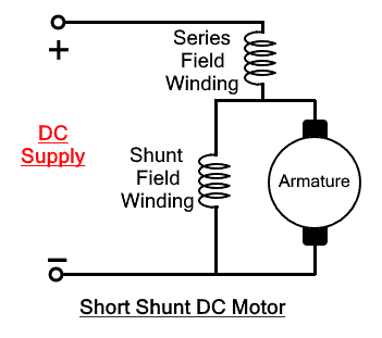
Short Shunt DC Motor
A motor is said to be a short shunt DC motor if the shunt field windings is only parallel to the armature windings & it is in series with the field windings as shown in the figure below. It is also known as compound wound motor.
Long Shunt DC Motor
A DC motor is said to be long shunt motor if the said shunt field windings is in parallel to the both armature winding as well as the field winding.

Permanent Magnet DC Motor (PMDC)
The Permanent Magnet DC motor or shortly known as PMDC motor is another type of brushed DC motor. It has the usual armature like the rest of brushed DC electric motors explained above. However, there is no stator or field winding, the magnetic field is generated using a permanent magnet placed in the stator.
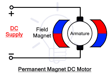
When the armature windings carrying the input current is placed inside the N & S poles of the magnet. The magnetic field interacts with it & the armature experience rotational force.
The permanent magnet generates a fixed magnetic field which is designed at the time of the construction & it can’t be changed after that. However, the strength of the magnet reduces with time. There is an extra excitation field found in some designs that helps increase its magnetic strength when it reduces.
PMDC does not need field excitation to generate the field flux as it is produced by the permanent magnet. This increases its efficiency as no extra power is consumed for excitation. The absence of the field windings greatly reduces the size of overall motor. Therefore PMDC motors have compact designs. They are also very cheaper & best for low power applications.
Related Post: Power, Voltage and EMF Equation of a DC Motor – Formulas
Brushless DC Motor
As the name suggests, Brushless or BLDC Motor is an another main type of DC motor that does not have any carbon brushes & commutators assembly. It means the input power is not supplied to the rotating part of the motor but to the stator of the motor which in this case is made of multiple windings & the rotor is made of a permanent magnet.
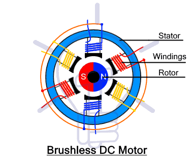
It has multiple stator windings each situated at a different angle to generate flux in different directions. The input is switched between the stator’s windings to generate a magnetic field that pushes & pull on the rotor’s magnetic field causing it to rotate in its direction. A Hall Effect sensor is used to detect the position of the rotor & switch the input to the correct stators winding respectively.
Since the DC input to the stator needs to be switched, such electric motors used electronic commutations instead of mechanical commutation using switching devices such as thyristors. These switches are controlled using microcontroller to precisely switch the input between the stators windings. It essentially switches the DC input into a 3-phase supply which generates a smooth rotating magnetic field.
The brushless motor speed depends on the frequency of the AC power supplied by the controller. Which is why it is also called synchronous motor
The controller used for brushless motor is more sophisticated & very expensive. It does no operate without its controller which also offers the precise speed control & positioning of the rotor. But the cost of the controller is far greater than the motor itself.
Since there are no brushes, there are no electrical or electromagnetic noises & the sparks generated in mechanical commutation. It helps in increasing the life span of the motor as well as the efficiency of the motor. The energy dissipated in brushes is converted into mechanical output. And they are also maintenance free.
Related Post: Difference Between Brushed and Brushless Motor
Coreless or Ironless DC Motors
As the name suggests, such DC motors have no laminated iron core. The rotor winding is wound in skewed or honeycomb shape to form a self-supporting hollow cage often made with using epoxy. The rotor made of permanent magnet sets in the hollow rotor.
The coreless design eliminates the issues & losses associated with the iron cores of the traditional motors. For example, such electric motors have no iron losses which increases the efficiency of the motor up to 90%. The design also reduces the winding inductance which reduces the sparks generated between the brushes & commutator thus increasing the lifetime of the motor. It also reduces the mass & inertia of the rotor which also increases the acceleration & deceleration rate of the motor.
Special Motors
There are several types of special electric motors that are the modified versions of other motor designed for special purposes. Some of these electric motors are given below.
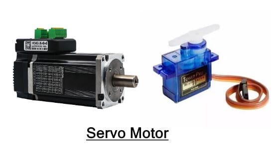
Servo Motors
Servo motor is a special type of motor used for pushing/Pulling or lifting or rotating an object at some specific angle. Servo motor can be designed to run on AC as well as DC power supply. Servo motor that runs on DC supply is called DC servo motor While those that runs on AC is called AC servo motor. It is a simple motor with a controller & multiple gears to increase its torque.
These motor are rated in kg/cm (kilogram per centimeter). It specifies much weight the servo can lift at a specific distance. E.g. a servo rated 3kg/cm can lift a load of 3kg that is at 1cm away from its shaft. The weight lifting capacity decreases with an increase in the distance.
The servo motor has a gear assembly, controller, a sensor and a feedback system. The gear assembly is used to decrease the speed & increase its torque significantly. The controller is used for comparing the input signal (desired position) & signal from the sensor (actual position of the servo) which is acquired through the feedback system. The controller compares these two signals & eliminated the error between them by rotating the motor shaft.
Servo motors has three wires. Two of them are used for providing the power supply while the third one is used for controlling the servo’s position. It is controlled by providing a pulsating signal thorough a microcontroller using PWM (pulse width modulation).
The servo can rotate 90° in either direction making it a total of 180° rotation. Neutrally it is in the middle position at 90°. It can rotate by varying the pulse width between 1ms & 2ms where 1ms corresponds to 0°, 1.5ms corresponds to 90° while 2ms corresponds to 180° angle of the shaft.
Direct Drive
Direct drive motor or also known as torque motor is another type of motor that produces high torque at low speed even when it is stalling. The payload is directly connected to the rotor thus eliminating the use of gearbox, belts, speed reducers etc. It is a brushless permanent magnet synchronous motor with no commutators & brushes. Since there is no mechanical wear & tear, it reliable & has a long lifetime. The fact that it has less mechanical parts means it require less maintenance and low cost.
Related Posts:
Linear Motors
The linear motor has an unrolled stator & rotor that offers a linear force instead of rotational force. If you slice any motor & lay it flat on a surface, you will get a linear motor.
The armature windings are designed in a linear fashion which carries 3 phase current to generate a magnetic field. the magnetic field does not rotate instead moves in a straight line. The magnetic field interacts with the magnetic field generated by the flat permanent magnet lying below it. The interaction between them generates a linear force upon each other thus the armature moves forward or backward.
It is an AC powered motor with a controller such as in servo motor. The power is supplied to the primary part of the motor that contains windings. It generates its own magnetic field whose polarity depends on the phase of the AC supply. The secondary part of the motor is permanent magnet whose magnetic field interacts with the magnetic field of the primary part & as a result attracts & repels it by generating a linear force. The amount of current determines the force while the rate of change of current determines the speed of the primary part.
Linear motors are used in robotics, medical device & factory automation etc.
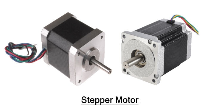
Stepper Motor
A stepper motor or a stepping motor is a brushless DC motor whose full rotation is divided into a number of equal steps. Such motor rotates in steps (fixed degrees) instead of rotating continuously. Such stepping movement offers great precision which is utilized is robotics.
The stepper motor operates on pulses. Each pulse moves the motor by one step. The precision of the motor depends on the number of steps per revolution. The steps size is determined during its design. However, the speed of the motor can be controlled by applying the pulse train of variable frequency. The controller inside the servo motor moves forward or backward the rotor by one step upon each pulse.
It is used for its accurate & precise positioning. It offers full torque at standstill. It has less maintenance requirement due to brushless design. Thus they are very reliable & has long lifetime.
Stepper motor due to its precise positioning is used in industrial machines used for automatic manufacturing of products, CNC based machines. It also found applications in medical instruments & machinery as wells as in security cameras. Stepper is widely used in electronic gadgets & other smart electronic systems.
Universal Motor
The Universal motor is a special type of motor that can run on AC as well DC power supply. it is a brushed series wound motor where the field windings is connected in series with the armature windings. They offer maximum starting torque with a high operating speed.
Since the windings are connected in series, the direction of the current through both windings remains the same even if the current direction reverses multiple times in a second. Although, the motor may run slower on AC due to the reactance of the windings.
Related Posts about Electric Motors:
- Why Motor rated in kW instead of kVA?
- Direct Online Starter – DOL Starter Wiring Diagram for Motors
- Cable Size Calculation for LT & HT Motors
- What is Motor Efficiency and How to improve it?
- Motor Protection – Types of Faults and Protection Devices
-
 Why are Inductive & Capacitive Reactances Measured in Ohms?
-
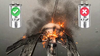 What Happens If You Install a Larger Capacitor in a Fan?
-
 Motor Capacitor Calculator – Calculate Fan Capacitor Value
-
 Why is a Capacitor Bank Rated in kVAR, Not in Farad?
-
 Why is the Rating of a Capacitor Expressed in Farad?
-
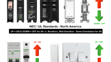 Why are the Breakers Switched Opposite to Light Switches?