Motor Protection – Types of Faults and Protection Devices
Types of Motor Faults and Protection Devices
Common Motor Failures and Faults
It is important to know and to understand motor failures and faults to define the most suitable protection devices for each case. You also must know about important terms related to motor control and protection.
Being non-static machines motors are subjected to electrical and mechanical stress.
Motor failures come in three basic types: electrical, mechanical and mechanical that progresses into electrical.
Common types of motor failure and faults are:
- Bearing failure
- Insulation breakdown
- Locked rotor
- Overheating
- Overloads (electrical and mechanical)
- Phase imbalance and any voltage imbalance will lead to an even higher current unbalance.
- Running in reverse
- Shaft misalignment
- Vibration
Overheating can occur from undersizing the motor, insufficient cooling at low speed when using variable speed drives (VSD), changes to the load on the motor such as jammed equipment and hot ambient conditions.
Insulation breakdown, leading to burnt windings, imply short-circuit either within the motor or within the power supply circuit for the motor, and may be caused by overheating, overloads and overvoltages.
About 80% of electrical motor failures are a result of winding damage in the motor stator and bearing faults.
Bearing failure on motors can be an indication of the incorrect bearings for the application.
A motor mounted vertically needs different bearings then a motor horizontally mounted. A motor driving a large or multi-belt drive will require bearings that handle big radial loads. A motor bolted to a distorted base plate will twist.
Bearings are usually small compared to other major motor components, making them particularly vulnerable to damage and wear; some studies blame more than half of all motor failures on bearing malfunction, most of which result from too little or too much lubrication. Another significant cause of bearing failure is misalignment.
Shaft misalignment will destroy bearings well before their full working life. The motor shaft must be directly in-line with the shaft it is driving what can only be achieved using precision alignment techniques such as laser.
Other problems that may occur with motors are:
- Water and dust ingress into the stator coils or the terminal housing leading to short-circuits
- Soft foot motor feet bolted down out of level
- Wrong motor mounting or housing type
- Electrical or mechanical unbalance
Noise indicates motor problems but ordinarily does not cause damage. Noise, however, is usually accompanied by vibration.
Vibration can cause damage in several ways. It tends to shake windings loose and mechanically damages insulation by cracking, flaking or abrading the material. Embrittlement of lead wires from excessive movement and brush sparking at commutators or current collector rings also results from vibration.
Finally, vibration can speed bearing failure by causing balls to “brinnell” sleeve bearings to be pounded out of shape or the housings to loosen in the shells.
Whenever noise or vibrations are found in an operating motor, the source should be quickly isolated and corrected.
What seems to be an obvious source of the noise or vibration may be a symptom of a hidden problem. Therefore, a thorough investigation is often required.
Noise and vibrations can be caused by a misaligned motor shaft or can be transmitted to the motor from the driven machine or power transmission system. They can also be the result of either electrical or mechanical unbalance in the motor.
Electrical unbalance occurs when the magnetic attraction between stator and rotor is uneven around the periphery of the motor. This causes the shaft to deflect as it rotates creating a mechanical unbalance. Electrical unbalance usually indicates an electrical failure such as an open stator or rotor winding, an open bar or ring in squirrel cage motors or shorted field coils in synchronous motors. An uneven air gap, usually from badly worn sleeve bearings, also produces electrical unbalance.
The chief causes of mechanical unbalance include a distorted mounting, bent shaft, poorly balanced rotor, loose parts on the rotor or bad bearings. Noise can also come from the fan hitting the frame, shroud, or foreign objects inside the shroud. If the bearings are bad, as indicated by excessive bearing noise, it is necessary to determine why the bearings failed.
Another problem motors can face is a long start time. If a motor is subjected to many successive starts, the rotor windings or rotor bars can be heated up to a point where the electrical connections between the rotor bars and the end rings are damaged.
Motor Protection Devices
No matter what rated voltage and size motors have they are protected against overcurrents (short-circuit) and overloads.
Small and medium size LV motors are usually only protected against overloads and short-circuits and large LV motors and MV motors have also other protections.
Overload and overcurrent protections must be designed to be insensitive to in-rush currents at starting time, to avoid untimely power interruption.
For LV motors the protection against overcurrents and short-circuits can be performed by fuses, associated to switch-disconnectors or instantaneous trip circuit breakers that respond to immediate (almost instantaneous) values of current from a short circuit, ground fault, or locked rotor current.
Inverse time circuit breakers have both thermal and instantaneous trip features and are preset to trip at standardized levels.
This is the most common type of circuit breaker used in the building trades for residential, commercial, and heavy construction.
The thermal action of this circuit breaker responds to heat. If a motor’s ventilation inlets and outlets are not adequate to dissipate heat from the windings of the motor, the heat will be detected by the thermal action of the circuit breaker.
If short-circuit should occur, the magnetic action of the circuit breaker will detect the instantaneous values of current and trip the circuit breaker.
Fuses usually are not suitable for the protection against overloads, because if sized to provide overload protection, they would blow when the motor starts due to high motor inrush current, although they can be used as an overload back-up protection.
Protection with fuses presents the risk of single-phasing damage to the motor when only one fuse blows unless single-phase protection is provided; this subject will be discussed later on this chapter.
Large size LV motors and MV motors are protected against short-circuits (phase-to-phase and phase-to-earth) by overcurrent relays (50; 50N; 51; 51N) connected to CT.
The protection against overloads is normally assured by thermal overload relay. This relay can be of the following types:
Bi-metallic Strip
A thermal overload protection will accommodate the brief high starting current of a motor while accurately protecting it from a running current overload. The heater coil and the action of the bi-metallic strip introduce a time delay that affords the motor time to start and settle into normal running current without the thermal overload tripping. Thermal overloads protections can be manually or automatically resettable depending on their application and have an adjuster that allows them to be accurately set to the motor run current.
Ambient temperature in which a starter and motor is located must be considered when selecting bi-metallic strip relays because a high ambient temperature reduces overload trip time.
Reduced overload trip time can lead to nuisance tripping if a motor is located in a cooler ambient temperature than the starter and leads to motor burnout when the motor is located in a hotter ambient temperature than the starter.
Most thermal overload devices are rated for use at a maximum temperature of 40 ºC, and a derating of the relay may be required.
Most relays are adjustable over a range from 85% to 115% of their value.
Some models are available with ambient compensation. An ambient compensated devices trip point is not affected by ambient temperature and performs consistently at the same value of current.
This type of relays is commonly used on low and medium size LV motors.
Standards and manufacturers’ data usually show recommended regulation set-point of this type of relays in accordance with rated power of the motor; same tables also show recommended rated currents of fuses (aM or gG type – see Section 2.4) and instantaneous circuit breakers that are associated to the relays for overcurrent protection, as shown in Table 3.
Table 3 – Rated fuses current for motor protection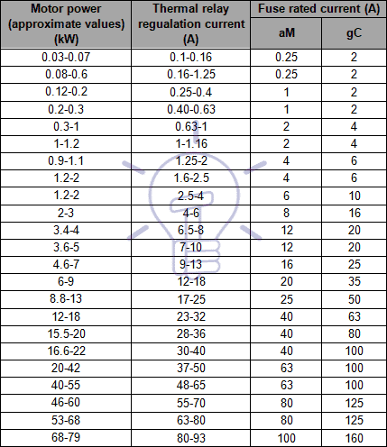
Electronic Digital Overload Relays
This type of protection is used for large LV motors and HV motors, and contains a microprocessor. These devices may model the heating of the motor windings by monitoring the motor current and they can also include metering and communication functions.
Common protection of large LV motors and MV motors is usually done by the following protection devices:
- Overload protection: 49
- Instantaneous phase overcurrent: 50
- Instantaneous earth overcurrent: 50N/50G
- Time delay phase overcurrent: 51
- Time delay earth overcurrent: 51N/51G
In some situations it is not recommended to protect motors against overloads; that is the case of fire fighting water pumps and smoke exhaust fans.
Very large LV motors and MV motors are expensive, and it is usually wise to provide more comprehensive protection schemes. Such schemes include:
- Bearing temperature monitors and protection (38)
- Differential protection (87M)
- Incomplete start sequence / long start time protection (66)
- Negative phase sequence (phase reversal protection)
- Overheating protection
- Phase unbalance or phase failure protection (47)
- Stall or locked rotor protection
- Under and over voltage protection (27 and 59, respectively)
- Vibration monitors and protection (39)
- Winding temperature monitors and protection devices
Differential Protection for LV & HV Motors
Differential protection is often provided for medium and large size motors with supply voltages of greater than about 4 kV, and electrically operated (shunt trip) circuit breakers. The differential protection provides high speed direction and clearance of faults on the motor stator windings.
Where the power supply system is solidly grounded the differential protection will detect both phase-to-phase and phase-to-ground faults.
With differential protection the current at each end of each winding is compared to determine when a fault condition exists.
This function requires two sets of CT, one at beginning of the motor feeder, and the other at the star point.
The differential protection function can only be used if both sides of each stator phase are brought out of the motor for external connection such that the phase current going into and out of each phase can be measured. The differential element subtracts the current coming out of each phase from the current going into each phase and compares the result or difference with the differential pickup level.
If this difference is equal to or greater than the pickup level a trip will occur.
Figure 19 shows an example of this protection.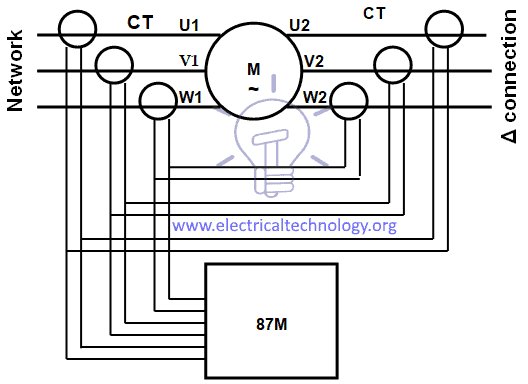
Figure 19 – Motor differential protection
Using six CT in a summing configuration, during motor starting the values from the two CT on each phase may not be equal as the CT are not perfectly identical and asymmetrical currents may cause the CT on each phase to have different outputs.
To prevent nuisance tripping in this configuration, the differential level may have to be set less sensitive, or the differential time delay may have to be extended to ride through the problem period during motor starting.
The running differential delay can then be fine tuned to an application such that it responds very fast and is sensitive to low differential current levels.
Windings overheating protection is usually done with Resistance Temperature Detectors (RTD) and thermistor and automatic shut down devices can be installed. Attaching a separate booster fan to aid the motor fan solves the overheating problem when a VSD is used to control the motor speed.
Incomplete start sequence / long start time causes rotor overheating.
As it is not possible to physically measure the heat of the rotor on squirrel-cage motors is necessary to determine the heat by measuring the current the rotor is drawing through the stator to excite the rotor. A thermal replica of the rotor is established using an I2t curve.
The restart inhibit will block the user from starting the motor if the relay determined that the rotor reached a temperature that will damage the rotor should a start be attempted. The relay will thus only allow a restart if the rotor has a sufficient thermal reserve to start.
Bearing protection is usually performed by RTD and thermistor to monitor the temperature.
Vibration protection uses sensors/accelerometers that are typically placed at key locations on the motor and bearings.
Since the bearings are the load carrying part of the mechanical drive train, accelerometers should be placed on the input and output
Figure 20 shows an example of vibration sensors and recommended locations.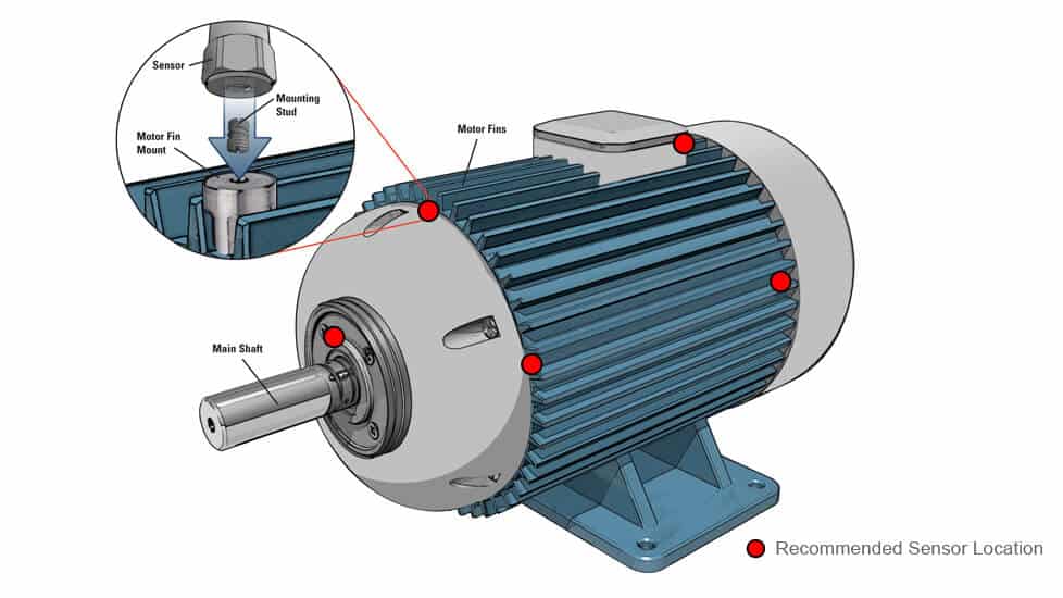
Figure 20 – Motor vibration sensors
Nowadays IED (see Section 2.1) that group all required protection functions are commonly used for large LV motors and MV motors.
![]()
Related Posts:
- Generator Protection – Types of Faults & Protection Devices
- Cables Feeder Protection – Faults Types, Causes & Differential Protection
- Overhead Lines Faults & Protection
- Power Transformer Protection & Faults
- Power Transformers Maintenance, Diagnostic & Monitoring
- Transformers Fire Protection System – Causes, Types & Requirements
- How To Locate Faults In Cables? Cable Faults, Types & Causes
- Fault Current Limiter and Their Types
- GFCI: Ground Fault Circuit Interrupter. Types, Working & Applications
- All About Electrical Protection Systems, Devices And Units


