Types of Inductors and Their Applications
Different Types of Inductors and their Applications
There are different types of inductors used in the industry. Each of these different types has some special uses & application such as filters, oscillators, isolator, etc. Therefore It is important to know about the specific type of inductor before buying it.
What is Inductor?
We have already shared a detailed post about inductors? You can read it here: What is Inductor – Its Working, Parameters, Factors & Applications
Below, we will discuss different types inductors based on different factors and their applications.
Such as:
- Air Core Inductor
- Ferromagnetic/Iron Core Inductor
- Ferrite Core Inductor
- Iron Powder Core Inductors
- Ceramic Core Inductors
- Laminated Steel Core Inductor
- Toroidal Core Inductor
- Drum/Bobbin Core Inductor
- Multi-Layer Inductor
- Thin Film Inductor
- Molded Inductor
- Coupled Inductor
- Power Inductor
- Radio-Frequency RF Inductor
- Chokes
- Variable Inductors
Types Of Inductors Based On Their Core:
The core of the inductor plays an important role in its characteristics. The material & design of the core specifies the inductance, current capacity & operating frequency of the inductor.
Based On Core Material
Some types of inductors classified according to their core material are given below:
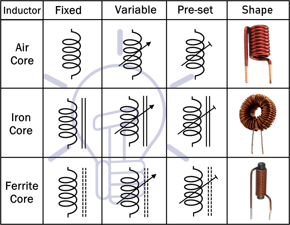
Air Core Inductor:
Air core inductors have non-magnetic core such as plastic, ceramic or just air as suggested by its obvious name.
Air core inductor uses any non-magnetic material as core to reduce the core losses i.e. eddy current & stray losses, especially when the operating frequency is very high. But the use of non-magnetic core also decreases its inductance.
They are widely used in RF applications because of their low losses at high operating frequencies.
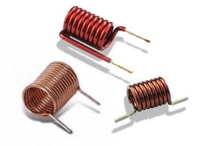
The main drawback of air core inductor is that mechanical vibration can affect its inductance.
- Related Post: What is a Solenoid and Solenoid Magnetic Field
Ferromagnetic/Iron Core Inductor:
Such type of inductor consists of a core that is made up of a ferromagnetic material. They are also known as iron core inductors.
Ferromagnetic materials are magnetic in nature & their magnetic core is used to increase the inductance of the coil significantly. It is because of the fact that the ferromagnetic materials have high magnetic permeability & they increase the magnetic field of the coil.
However, there are some drawbacks of using ferromagnetic core in the form of losses called core losses. The core losses comprise of the eddy current loss & hysteresis loss.

The design & use of different types of ferromagnetic materials for the core of the inductor causes a huge impact on its performance. This is why ferromagnetic core inductors are classified in many types.
Related Posts:
Ferrite Core Inductor:
These types of inductor use ferrite core. Ferrite is a material with high magnetic permeability made from the mixture of iron oxide (ferric oxide, Fe2O3) & a small percentage of other metals such as nickel, zinc, barium, etc.
There are two types of ferrites i.e. Hard Ferrites & Soft Ferrites.
- The Hard ferrites are used in permanent magnets as they do not demagnetize very well. They are not used in inductor because of their high hysteresis loss.
- While Soft ferrites magnetization changes easily & are a good conductor of the magnetic field. Thus they are used in transformer & inductors.
The ferrite core has very low electrical conductivity which reduces the eddy current in the core, resulting in very low eddy current loss at high frequency. Hence they can be used in high-frequency applications.
The Ferrite material is very cheap as it is almost made up of iron rust and is very resistant to corrosion.
Iron Powder Core Inductors:
The core of such kind of inductors is made up of a mixture of iron grains with an organic binder such as epoxy resin etc.
The epoxy insulation coating over the iron particles reduces the eddy current loss in the core. Since the size of the particles determines the eddy current flow in the core. Smaller the particle’s size, lesser the eddy current induced.
The air gap between the particles of the core is evenly distributed which decreases the magnetic permeability of the core. Therefore the saturation current of this core is relatively very high.

But as we know iron cores are highly susceptible to core losses at high frequency. Thus, they are used for frequency below 100 KHz. Due to their higher saturation current, they are used in high power application mostly in chokes such as storage chokes, dimmer chokes, filter chokes, etc.
The iron powder is very cheap which makes such kind of core design much cost efficient if the size does no matter.
Related Posts:
Ceramic Core Inductors:
Ceramic is a non-magnetic material just like air. Ceramic cores are used to provide a shape for the coil & a structure for its terminals to sit upon. As it is a non-magnetic material, it has low magnetic permeability & low inductance. But it provides a reduction in the core losses. It is mostly available in SMD packaging & is used in applications where low core losses, High Q & low inductance are required.
- Related Post: Types Of Capacitors – Fixed, Variable, Polar & Non-Polar
Laminated Steel Core Inductor
In such type of inductors, the core is laminated which means that it is made up of a bunch of thin sheets placed on top of each other in a tight form. The sheets are coated with insulation to increase its electrical resistance & prevent eddy current flow between them. Therefore the eddy current loss in laminated core inductors decreases significantly. They are used in high power applications.
Based On Core Design
The geometry of the core also plays a role in the inductor’s performance. Some of these designs are given below:
- Related Post: Types of Transformers and Their Applications
Toroidal Core Inductor
As the name suggests these types of inductors have a toroidal core which is a circular ring or donut shape core. The core is made of ferromagnetic material.
The advantage of this circular core is that the magnetic field is contained within the core & there is very low magnetic flux leakage. Due to Low leakage flux, the magnetic field in the core is higher. This increases the inductance of toroidal core inductor & it is higher than rod or bar-shaped core inductors having the same material.
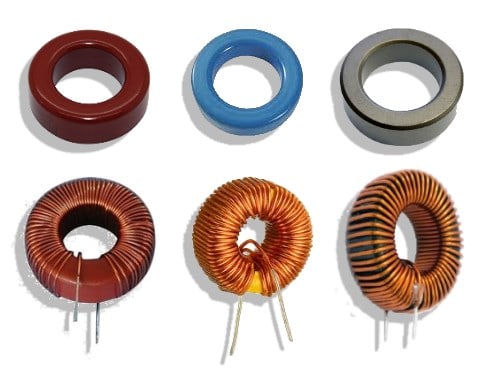
The other important aspect of the toroidal core is that the core emits less electromagnetic interference (EMI) in comparison to the other inductors. Which is why they are preferred in designing compact devices, where the components are very close to each other.
They are used in power supplies, control circuits, communication systems & medical devices, etc.
- Related Post: Types of Diodes and Their Applications
Drum/Bobbin Core Inductor:
This type of inductor is made of a bobbin-shaped core. It is a cylinder with two flat discs at each end. It is also known as drum core inductor.
The coil is wounded around the cylinder. The bobbin core does not provide a closed magnetic path instead the flux goes through the disc into the air gap & then enters the core through the second disc at the other end. It provides a large air gap for its magnetic field to store more energy. And therefore increases the saturation current of the inductor. This means that the inductor can withstand high peak currents without saturation but at the cost of electromagnetic interference (EMI) radiation.
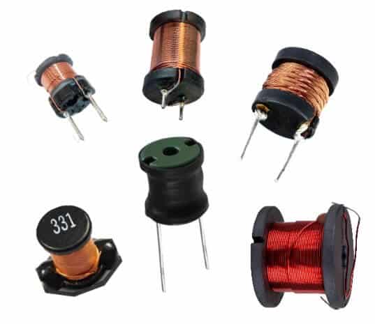
There are two types of bobbin core inductor i.e. shielded & un-shielded.
- Shielded bobbin core inductors have an extra layer over the top of winding to complete the flux path containing the magnetic field inside the core. Such types of inductors have low EMI due to low flux leakage & high inductance due to an increase in magnetic permeability but at the cost of low saturation current compared to un-shielded core inductor.
- Unshielded bobbin core inductor is discussed above which lacks a closed flux path and have high saturation current at the expense of low inductance & EMI.
The unshielded core inductors are cost effective. They are used in power conversion applications where the peak current is large. They are available in axial, radial & SMD packaging.
- Related Post: Different Types of Sensors with Applications
Types of Inductors Based on Their Usage
Inductors are designed for different usage. Their design varies from application to application where some of these inductors based on its usage are given below.
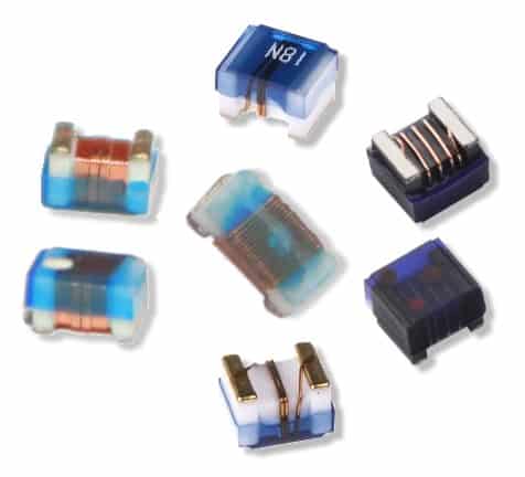
Multi-Layer Inductor:
As the name suggests, these inductors have multiple layers of wire wounded on top of each other. Such inductors have large inductance due to an increase in the number of turns of the winding.
Multi-layer inductors are available in SMD (surface mount devices) packaging.

The SMD multilayer inductors have multiple layers of conductive traces on top of each other separated by a ferrite material. These traces act as the coil of an inductor. However, due to an increase in the number of turns of the coil, the parasitic capacitance also increases. This reduces the Q factor of the inductor which can be improved by using ceramic dielectric material because ferrite cores have losses at very high frequency.
They are used in mobile communication devices due to their compact SMD design.
Thin Film Inductor:
Such type of inductor is designed on a substrate of thin ferrite or magnetic material. A conductive spiral shaped trace of copper is placed on top of the substrate. The design allows stability & resistant to vibrations.
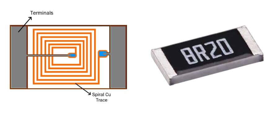
Due to Its high accuracy, performance & compact size, it is used in mobile communication devices, wireless networks & power supplies, etc.
Molded Inductor
Such type of inductor is coated with insulation such as molded plastic or ceramics just like the resistors.
The core is made from ferrite or phenolic material. The winding can be in different designs & it is available in different shapes like axial, cylindrical & bar shape. They are available in SMD & THT as well. Their miniature size & light weight allows them to be used in PCB (Printed circuit boards), mobile devices & computers, etc.

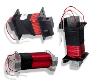
Coupled Inductor
Couple inductors are made of two windings around a common core.
The changing magnetic flux due to first winding induces emf in the second winding; this phenomenon is known as mutual inductance. These both winding are electrically isolated. Thus coupled inductor provides electrical isolation between two circuits. A Transformer is a coupled inductor.
They have multiple applications depending on their winding. 1:1 winding ratio inductors are mostly used for electrical isolation or increasing the series inductance. Winding ratio of 1: N coupled inductors (which can step up or step down voltages) are used in other energy conversion circuits such as flyback, SEPIC, ZETA, etc.
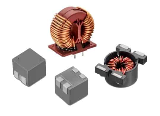
Power Inductor
These inductors are specifically designed to withstand high current without reaching the magnetic saturation region. To increase the saturation current rating, the magnetic field of the inductor is increased, which causes EMI (Electromagnetic interference). To reduce the EMI, most power inductors are used with proper shielding. They are available from few amps to a few hundred amps in both SMD & through-hole packaging.
- Related Post: Types of Switches -Construction, Working & Applications
Radio-Frequency RF Inductor
Such types of inductors are designed for high-frequency applications. A general inductor does not perform very well due to its high impedance and core losses at high frequency. Most of these losses occur due to parasitic capacitance, skin effect, proximity effect & core loss (eddy current loss), etc.
The eddy current loss is directly proportional to the frequency. Thus it is eliminated by entirely removing the core, instead of using air core inductor.
While the parasitic capacitance is caused due to the potential difference between the turns of winding that are at close proximity. It causes the inductor to self-resonate at high frequency. It is reduced by maintaining some space between the wires & wounding the coil in a spider web or basket weave (honeycomb) design to avoid parallel turns.

The skin & proximity effect is caused due to the increase in the frequency which increases the resistance of the wire. This high frequency causes skin effect where most of the current flow on the surface of the wire, due to increased resistance inside the wire where little to no current flow. Proximity effect has the same outcome but it is because of the induced eddy current between two wires in close proximity which forces the current to flow on the surface of the wires. To reduce the resistance due to these effects the winding is made of strips to increases the surface area.
- Related Post: Types of Batteries and Cells and Their Applications
Chokes
Choke is just a simple inductor but it is specifically designed for blocking (choking) high-frequency signals. The impedance of a choke increases significantly with the increase in the frequency. Therefore it blocks high AC current and allows DC & low-frequency AC current with some loss.
The Inductors that are used as chokes are constructed without using any of the impedance reduction techniques which are used to increase its Q-factor. The chokes have low Q-factor & it is designed this way deliberately because we want its impedance to increase by increasing the frequency.
There are two types of Chokes i.e. AF chokes & RF chokes. The AF (audio frequency) choke is used for blocking Audio frequency and only allowing DC current. While the RF (radio-frequency) chokes are designed to block RF frequency while allowing DC & audio frequency.
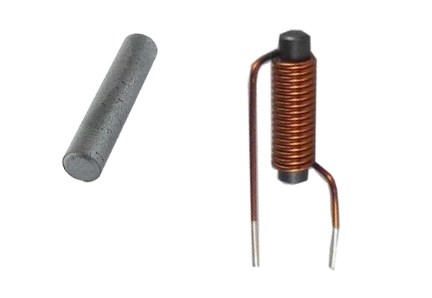
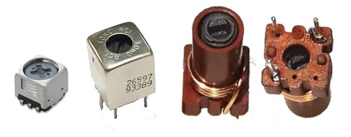
Variable Inductors:
As the name suggests, these inductors are designed to have variable inductance. This variable inductor is designed in more than one possible ways.
The most common design of variable inductor is having a movable ferrite core. Moving the core along the winding will increase or decrease the permeability which affects the inductance of the inductance. The core can be designed to slide or screwed in or out of the coil.
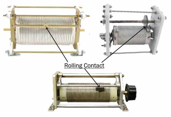
Another method of variable inductor design is to increase or decrease the number of turns through movable contact on top of the windings. The conductor used in these windings have no insulation (so the core must be insulated), thus moving the Contact on top of the turn will change the number of effective turns. As the number of turns is directly proportional to the winding, the inductance varies accordingly. But the downside of such a method is that the contact short more than one turn which increases the loss in the winding. This issue can be resolved by increasing the space between individual turns and use a grove wheel as a contact. Such type of variable inductor is known as roller inductor.
- Related Post: Types of Rectifiers and Their Operation
The most efficient method is the use of variometer. It provides a continuous change in inductance. The variometer is made up of two coils (one inside the other) connected in series having 1:1 ratio. The mutual induction between these two coils plays the entire role in varying the total inductance. The inner coil can be rotated using a shaft which changes the direction of the magnetic field lines created by that coil.

When the magnetic fields are in the same direction it adds up & provides maximum inductance. When their directions are perpendicular to each other the inductance decrease. When they become totally opposite to each other the magnetic fields cancel out each other and the total inductance is minimum.
Related Post: