What is Double Tapped Breaker and Double Lug in Main Panel
Double Tapping at Breaker and Double Lugging in Electrical Panels – How To Identify and Solve the Issue?
What are Double Tapped Breakers and Lugs?
Double Tapping
A double tap at a circuit breaker refers to a wiring condition where two separate conductors (wires) are connected to a single breaker terminal that is designed for only one conductor. In other words, two wires are placed under one breaker screw or clamp instead of one.
If the breaker is designed to accept only one wire, a double tap considered as an issue as wires may not be securely are fastened as per termination guidelines.
Double Lugging
Double lugging at the service lugs occurs when multiple conductors are terminated under a single lug located ahead of (line side of) the main breaker. Service lugs are designed to accept only the incoming service conductors or feeder cables (Hot + Neutral for a 120V , or two hot conductors for a 120/240V system) coming from the main disconnect to supply utility power to the panel or load center.
These lugs, usually located at the top of the panel ahead of the main breaker, are generally not rated to accept more than one conductor per terminal unless specifically listed for that purpose.
A double-lugged connection at the service lugs is a serious safety concern because the additional conductors are not protected by a dedicated circuit breaker. As a result, they lack proper overcurrent and short-circuit protection, which can lead to overheating, equipment damage, or fire hazards.
Click image or open in a new tab to enlarge
How to Identify a Double Tap
In a 120/240V panelboard, a normal breaker connection should have one conductor per terminal. A double tap occurs when two branch-circuit wires are inserted into the same breaker lug.
For instance, correct way of termination is when a 1 breaker is connected to 1 wire which feeds one branch circuit.
Double tab is when a one breaker is connected to two wires feeding two branch circuits.
Similarly, double lugging is identified by looking for two or more electrical wires connected under a single screw terminal (lug) on a neutral bar, or main lug.
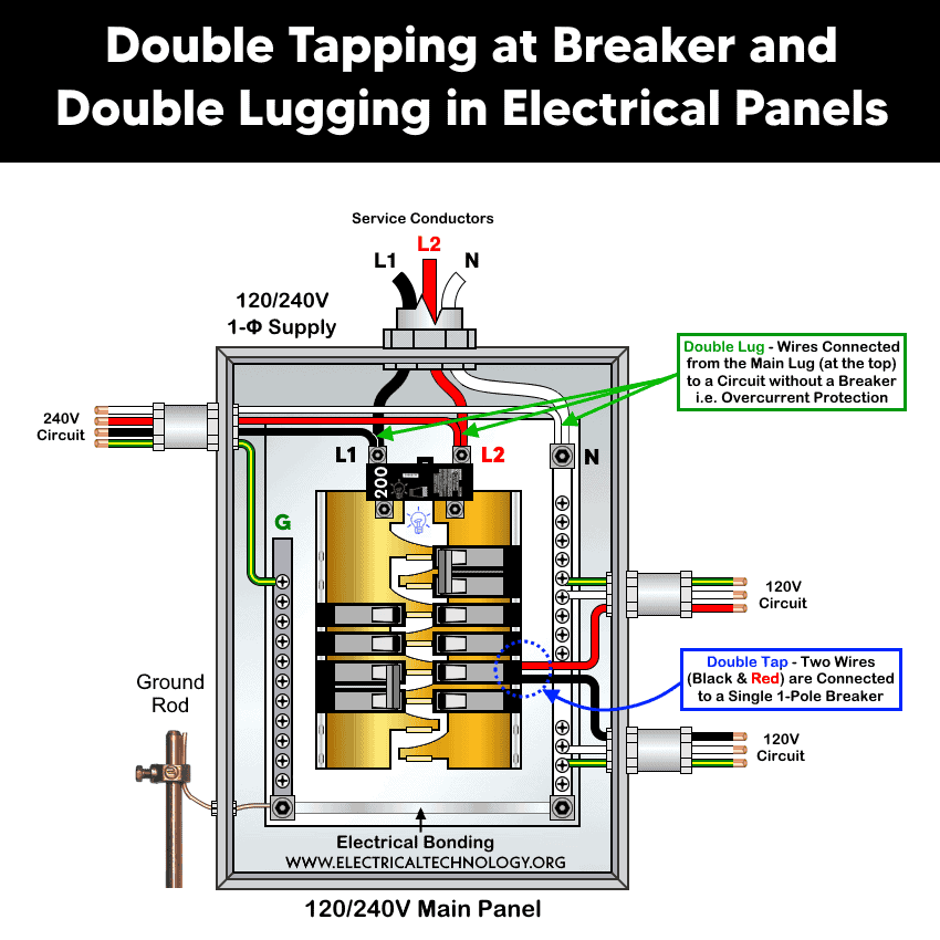
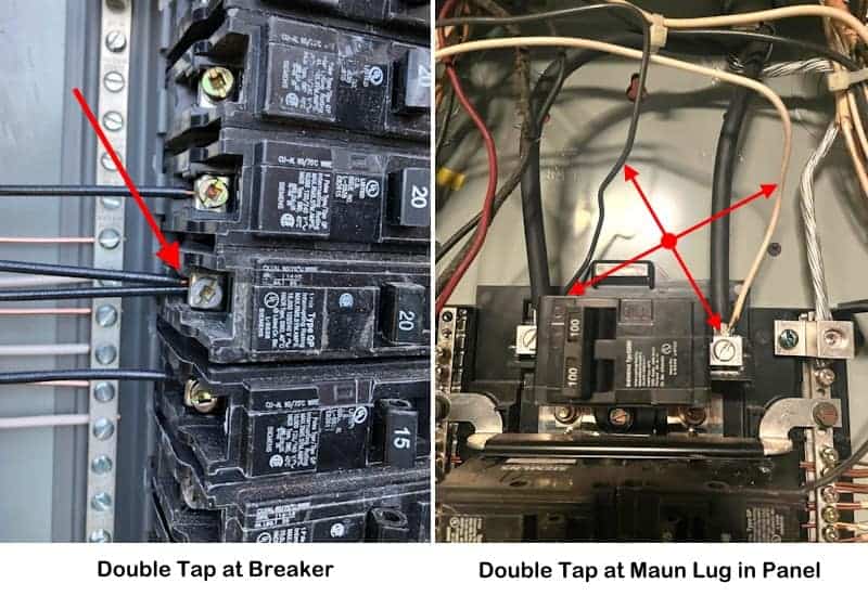
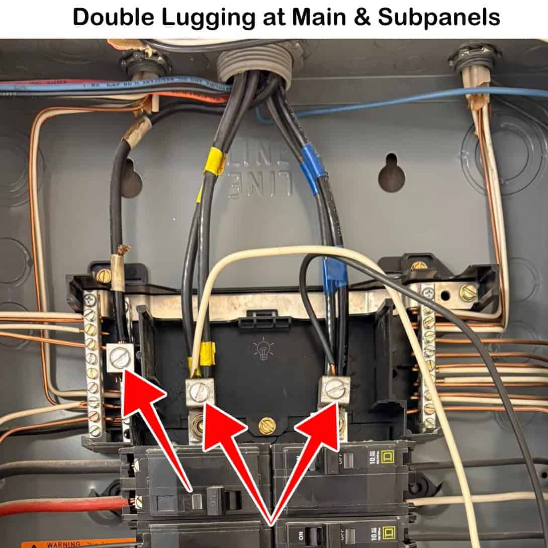
The following figure illustrates both double tapping at a circuit breaker and double lugging at the main panel.
Similarly, the following fig shows double lugging at main / subpanels with both hot lugs and neutral neutral terminal. This case is only acceptable if the lugs are rated for it.
Why Double Tapping is a Problem
Most standard circuit breakers are not listed for two conductors. If two or more electrical wires are connected to a single terminal (or “lug”) on a breaker that is designed to hold only one, it can lead to several issues as follows:
1. Loose Electrical Connection
Breaker terminals are designed to clamp one conductor securely. Two wires may not be held evenly, causing a loose connection.
2. Overheating
A poor connection increases contact resistance, which can lead to:
- Heat buildup
- Insulation damage
- Potential fire hazard.
3. Code Violation
According to the National Electrical Code (NEC), conductors must be terminated only in terminals identified for the number of conductors used (see NEC 110.14(A)). In short, double lugging or double tapping at the main neutral bus bar is more dangerous and hazardous than double-tapped circuit breakers.
When Double Tapping is Allowed
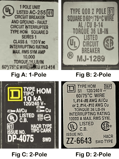
Some breakers are specifically designed and listed for two conductors from different manufacturers such as, Square D by Schneider, Siemens and Eaton (Cutler Hammer).
These breakers have dual-rated terminals that safely clamp two wires. However, this must be clearly indicated on the breaker label or documentation.
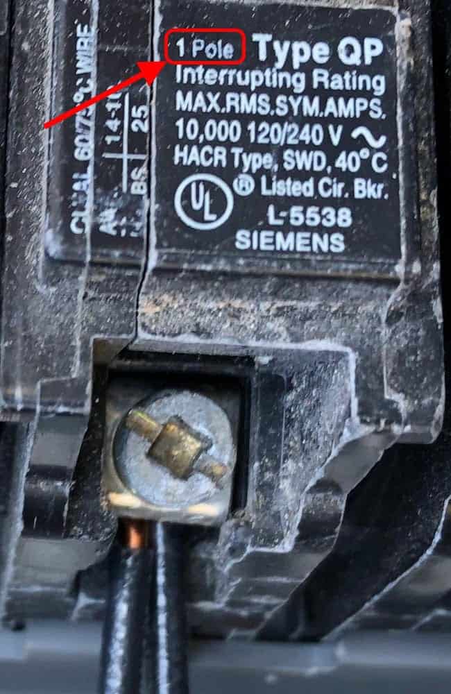
For instance, if a sign, letter, or mark printed on the side or front label of the breaker shows “2-P”, it means the breaker is a 2-pole breaker, and two conductors (wires) are allowed to be connected.
Solutions for a Double Tapping
Fixing Double Tapped Breakers
Double tap can be easily fixed by installing an additional breaker, pigtail connection or using a listed tandem (twin) breaker.
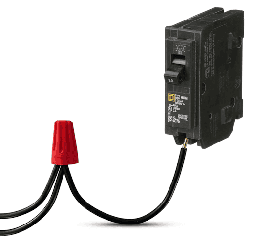
1. Pigtail Connection
The easiest way to fix a double tapped breaker is to add a pigtail connection. In this approach, two wires are joined with a short wire through wire nut and then connect that single short wire (pigtail) to the breaker.
2. Install a New Breaker
Install an additional circuit breaker in the main panel. Remove one of the double tapped wire and connect to the newly installed breaker. This approach is only possible if there are additional slot(s) in the load center.
3. Replace with a Tandem Breaker
If there is no additional space available in the panel for another breaker, you may remove the affected breaker and replace it with a tandem breaker (also known as a duplex breaker). A tandem breaker is a set of two breakers that fits into a single panel slot and occupies the space of one standard breaker.
This option is only possible if it is allowed by the panel manufacturer, because not all electrical panels are designed to accept tandem breakers.
Fixing Double Tapped Lugs
Similarly, to correct a double-lugged service connection, install a separate, properly rated circuit breaker in the main panel, instead of making a direct and unsafe connection at the service lugs. Then connect the branch circuit conductors to that breaker with proper neutral and ground connection.
Alternatively, install a subpanel supplied through a circuit breaker in the main panel. The subpanel can then accommodate additional breakers to feed branch circuits with proper overcurrent protection.
Precautions:
- Always disconnect the power supply by switching OFF the circuit breaker at the main service panel before performing any electrical work.
- If you are unsure about any part of the installation, consult a licensed electrician and ensure compliance with applicable local electrical codes.
Disclaimer: Electrical work is dangerous. The author assumes no responsibility for any loss, injury, or damage resulting from the use or misuse of this information, including improper circuit installation.
Resources:
Related Posts:
- National Electrical Code (NEC) Requirements for Panelboards
- Busbar, Bus Stab, Breaker Slot and Circuit Space in a Panel
- What Happens if the Neutral is Lost in the Main or Subpanel?
- Why Must Neutral and Ground Wires Be Bonded in the Main Panel?
- Why are Neutral and Ground Wires Separated in a Subpanel?
- Should GFCI Protection Be in the Main Panel or Receptacle?
- Difference Between BR and CH Breakers and Load Centers
- Difference Between Homeline and QO Breakers and Panels
- Difference Between 1-Pole and 2-Pole Breakers – NEC & IEC
- Can the Neutral Wire Cause Electric Shock? Different Cases
- Will I Get an Electric Shock If I Touch the Ground Wire?
- Will a Man Get an Electric Shock If He Hangs on a Live Wire?
- What Happens When You Touch an Electrical Busbar?
- Can We Use AC Circuit Breaker for DC Circuit & Vice Versa?
- Can I Use a 240V Breaker on a 120V Circuit and Vice Versa?
- Can You Use 15A Breaker on 20A Circuit and Vice Versa?
- What is the White Powder on the Circuit Breaker Terminals?
- Why Doesn’t a Standard Breaker Protract Against Ground Faults?
Sizing & Rating
- How to Size a Load Center, Panelboards and Distribution Board?
- How to Determine the Right Size Capacity of a Subpanel?
- How to Size a Circuit Breaker? Breaker Size Calculator
- How to Determine the Number of Circuit Breakers in a Panel Board?
- How to Find the Right Wire Size for 100A Service 120V/240V Panel?
- What is the Correct Wire Size for 100A Breaker and Load?
- How to Find the Number of Lights on a Single Circuit Breaker?
- How to Size a Breaker and Wires in AWG with EGC for Load?
- How to Size a Branch Circuit Conductors with Protection?
- How to Size Feeder Conductors with Overcurrent Protection
- How to Size Service-Entrance Conductors and Feeder Cables?
- How to Size Equipment Grounding Conductor (EGC)?
- How to Size Grounding Electrode Conductor (GEC)?
- How to Find the Proper Size of Wire & Cable In Metric & Imperial Systems
Wiring Tutorials
- How to Wire 120V & 240V Main Panel? Breaker Box Installation
- How to Wire a Subpanel? Main Lug Installation for 120V/240V
- How to Wire 120V & 208V – 1 & 3-Phase Main Panel? 3-Φ Load Center Wiring
- How to Wire a GFCI Circuit Breaker? 1, 2, 3 4 Poles GFCIs Wiring
- How to wire a GFCI Outlet? GFCI Wiring Circuit Diagrams
- How to Wire an AFCI Combo Switch – AFCI Switch Wiring Diagrams
- How to Wire a Single-Pole Circuit Breaker in a 120/240V Panel
- How to Wire a Two-Pole Circuit Breaker in a 120/240V Panel