Emergency Generator Set – Construction, Installation, Maintenance & Wiring
An Overview of Emergency Generator Set
Introduction to Emergency Generator Set
Hospitals, airports, shopping malls and office buildings, just to mention some examples, are very sensitive, in what concerns safety of people and goods, to power outages caused by faults in medium (MV) and low voltage (LV) distribution networks and even in high voltage (HV[1]) transmission networks.
When a power outage occurs is necessary that communication systems, emergency lighting, smoke exhaust fans, fire fighting water pumping stations, security, lighting in buildings and other critical electrical systems and equipments, designated as essential loads (or critical), continue running.
To solve such problems common solution is the installation of LV diesel emergency generator sets, whose applications, characteristics and installation procedures must be in accordance with IEC[2] Standard 60034.
Rated Power and Neutral Grounding of Emergency Generator
Rated power of LV diesel emergency generator sets[3] depends on the operation regime: standby, prime and continuous, as defined in ISO[4] Standard 8528.
In standby regime the available power supplied by the generator set varies with the value of the load during the lack of normal power supply and average power output is 70% of emergency standby power rating. Typical operation of this regime is 200 hours per year with a maximum of 500 hours per year.
In prime regime the available power supplied by the generator set varies with the value of the load for an unlimited period of time and average power output is 70% of prime power rating. Typical peak demand of 100% of prime-rated ekW[5] with 10% of overload capability for emergency use for a maximum of 1 hour each 12 hours; overload functioning may not exceed 25 hours per year.
In continuous regime output is available without varying load for an unlimited time. Average power output is 70 – 100% of the continuous power rating. Typical peak demand is 100% of continuous rated ekW for 100% of operating hours.
According to the definitions stated above is easy to understand that the same generator set has different rated powers for each operation regime. Rated power in standby regime is higher than rated power in prime regime, which is higher than rated power in continuous regime.
Rated power of generator sets main be defined in kVA or kW for a cos Φ (Power Factor)[6] = 0.8. It is also necessary to define the network frequency (50 Hz or 60 Hz).
In Table 1, as an example, are shown the values of rated power (kVA) of some generator sets of the same manufacturer and the same manufacturing series, according to the operation regime (f = 50 Hz).
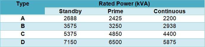
Table 1 – Examples of emergency generator sets rated power according to operation regime
As the LV network that the generator set wills electrically supplies is isolated and has unbalanced loads, neutral point of the windings of the alternator[7] is directly earthed since this neutral grounding system improves the behavior of the alternator with those types of loads.
Construction and Components of Emergency Generator
General Considerations
Main components of a generator set are (see Figure 1):
- Engine
- Alternator
- Main assembly/Frame.
- Starting battery and charger.
- Lubrication system.
- Cooling and exhaust systems, including the radiator.
- Fuel system.
- Voltage regulator
- Exhaust piping and silencer.
- Control and monitoring panel.
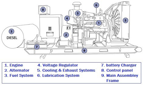
Figure 1 – Main components of a generator set
Engine
The engine that must be in accordance to ISO Standard 3046 is an internal combustion machine, four stroke cycle and usually diesel fueled (there also models gas fueled). The power of the engine must be suitable for the rated power of the alternator.
Main components of the engine are:
- Electronic speed governor, usually with a variation of ± 0.25
- Acceleration control and run and stop lever
- Standard steel ring to assure a rigid connection to the coupling system of the alternator enclosure
- Flywheel and elastic union for alternator coupling
The engine must start and work at least 8 hours at full load, followed by 1 hour of 10% overload under the specified temperature conditions. The engine must have electrical start-up, which time shall not be higher than 10 s.
Engine cooling may be done by circulation of air or water, in a close circuit with a radiator. To improve engine start-up it must be envisaged an oil, water or combustion air pre-heating system (usually resistors), which must work with the temperature increase of carter grease.
Alternator
The alternator is of synchronous type, single or three-phase, self excited, regulated and ventilated; the ventilation of the alternator shall be performed by a shaft coaxial turbine.
Main characteristics of alternators are:
- Rated voltage: 230 V (single-phase alternators); 400/230 V (three-phase alternators).
- Rated frequency: 50 Hz or 60 Hz.
- Rated power (depending on the operation regime – see Section 2).
- Power factor: usually 0.8.
- Insulating class: usually H.
Insulating class of alternators are established, according to IEC Standard 60085, taking into account the maximum temperature windings can withstand, since temperature is often main factor that contributes for insulating material ageing. In Table 2 are shown the alternators insulating classes.

Table 2 – Insulating of alternators
Other characteristics of alternators that must be considered are:
- Radio interferences suppression.
- Harmonic distortion: ≤ 2 % off-load; ≤ 3.5 % with balanced load.
- Voltage regulation: ±1.5% for off-load and full-load variations, power factor between 8 and 1 and speed variations of ± 4.5 %.
- Capability to recover voltage up to 3% of rated voltage within 3 s, when full-load is suddenly applied with cos Φ = 0.8.
- Capability to withstand short-circuits currents up to 300% of rated current during 5 s before the actuation of internal protection devices.
Other Components and Systems
The assembly frame of the engine and alternator (and even of the daily diesel tank) is usually constructed with standard steel profiles, electrically welded, and anti-vibrate supports shall be installed; these profiles must be calculated in order that the self vertical oscillation should be around 7 Hz.
The starting battery is lead-acid type and connected to a battery charger that will assure the maintenance charge of the battery and is normally installed in the control and monitoring panel.
Exhaust piping must include a silencer (see Figure 2) and a flexible connection from exhaust outlet of the engine to the outgoing pipe. Both silencer and piping must be thermally insulated with glass wool covered with aluminum sheet.

Figure 2 – Exhaust piping of a generator set
Fuel system includes the daily tank (with level indicator and maximum and minimum level switches) and must have such a capacity that assures the generator set woks during a defined time period, at full-load rated power for the established operation regime.
This system may also include an eventual diesel cistern, transfer pumps of daily tank (manual and electrical) and the required piping.
Control and Monitoring Panel
In the control and monitoring panel it shall be Installed the following equipment:
- Metering equipment (ammeters; voltmeters; frequency meter).
- Control and monitoring equipment: start and stop push-buttons; oil manifold; water thermometer.
- Control switch with 4 positions: Automatic/Manual/Test/Out-of-service.
- Start and stop generator set automatic system.
- Circuit breaker for alternator protection.
- Monitoring lamps.
- Emergency shutdown system of the engine.
- Battery charger (see Section 3.4).
- Control and monitoring equipments for all the auxiliary components of the generator set.
Installation Procedures of Emergency Generator Set
Generator sets are usually installed indoors, in a dedicated room, which must be provided with incoming and outlet grilles, calculated to assure the required air flow for equipment cooling.
Outgoing air grille is installed face to the radiator and shall allow an easy dismantling for generator set removing. In situations where is not possible to assure the required air flow for generators set cooling it is necessary to install radiator separated from the engine.
In these situations generator set cooling is done through fresh water circulation in a close circuit, using a centrifugal pump. Temperature is thermostatically controlled and heat dissipation is achieved by radiator, installed at the primary circuit, and a fan. The radiator must have a low noise level and must be mounted on anti-vibrate supports.
Figure 3 gives an example of what was explained above.
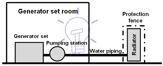
Figure 3 – Installation scheme of a Generator set with separated radiator
If the noise level of the generator set is too high according to noise regulations, namely in circumstances where the equipment is installed outdoors, the generator set must be installed inside an enclosure, as shown in Figure 4.
Figure 4 – Generator set inside an enclosure
Maintenance of Emergency Generator Set
As referred in Section 1 generators sets play a critical role in safety of people and goods of certain electrical installations and for that reason is important to establish an accurate maintenance program that must include:
- Run monthly, or twice a month, at off-load conditions for a period of 4 hours (to assure that it will run when necessary).
- Manual running.
- Generator set start in case of absence of network voltage and verification of the functioning of the automatic inverter switch.
- Visual inspection.
- Verification of earthing connection of neutral and all metallic parts.
- Verification of oil level and
- Battery status (visual inspection; voltage measurement of the elements; situation of the electrolyte).
Generator Start-Up. Automatic Transfer System
Generator set start-up shall me automatic, when there is an undervoltage or a negative sequence voltage in the power supply network and it is done through an automatism system installed in the generator set control and monitoring panel. This automatism system will provide also the disconnection and the stop of the generator set when the network voltage returns to normal.
The above referred automatism system will control the automatic transfer system, hereafter referred as automatic inverter switch, and must assure a number of start-up consecutive trials (never less than 3) with a time between trials that is the required time for battery regeneration.
Automatic inverter switch, which preferably shall be installed in the main incoming switchboard, must provide transfer of essential loads to the generator set power supply when a disturbance in the network voltage occurs and provide the re-transfer of those loads to network power supply when the situation backs to normal.
The automatic inverter switch may be built with 2 of the following equipments:
- Circuit breakers.
- On-load switches.
- Contactors.
Those equipments must have a mechanical and electrical interlocking to avoid the parallel association between the network and the generator set.
All switchboards must have disconnecting equipment (circuit breaker; on-load switch; contactor) to split the loads between essential and non essential, to avoid these loads to be powered by the generator set.
Figure 5 shows an example of a schematic diagram of a transfer system.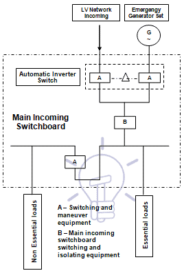
Figure 5 – Schematic diagram of transfer system
Wiring & Connection of Portable Generator
You can wire and connect a portable generator to the home supply system by three methods here.
[1] HV: Us ≥ 60 kV; MV: 1 kV < Us ≤ 49.5 kV; LV: Us ≤ 1 kV. Us is the rated voltage of the network. [2] IEC: International Electrotechnical Comission. [3] Hereafter we will use the expression generator sets to refer to LV diesel emergency generator sets. [4] ISO: International Organization for Standardization.


nice brother
Thanks so much for the post.Really thank you! Keep writing.
Thanks for educating me. But sir I need complaint guild on solar system. Thanks