All About Electrical Protection Systems, Devices And Units
Electrical Protection Units And Systems
This is a long and descriptive article on different types of protection for electrical systems and networks. In this article, you will be able to cover the different electric protection methods, system and devices, grading and protection, overhead lines protection, power system protection, cables feeder protection, transformer protection, motor protection ,generator protection, capacitor banks protection, bus bar protection, voltage and frequency protection and much more. Bookmark this post in case for later read.
Introduction to Electrical Protection Systems
HV, MV and LV[1] electric installations and equipments are subjected to internal and external faults that can cause serious damages in persons and other equipments.
To avoid and to minimize the consequences of those faults protection devices associated to equipments that are able to break electric current are required.
For a better understanding of protections devices, at each Section that covers protection systems of equipments and installations most common faults on those equipments and installations.
It is also important to refer that all units of mechanical and electrical parameters and their multiples and submultiples that are involved in the protection systems are in accordance with SI (Internation Units System); exceptions are made when hours (h) may be used instead of seconds (s) and the unit choosen for temperature is °C (celsius) instead of K (kelvin) – [K] = [°C] + 273.15.

Protection Devices and Technology
Protection Devices
In order to minimize the time of a fault switchgears and equipments are provided with protective devices to detect them and to isolate the faulty part of installation.
It is required firstly, the early detection and localization of faults, and secondly, the prompt removal from service of faulty equipment, in order to:
- To safeguard the entire system to ensure continuity of supply.
- To minimize damage and repair costs.
- To ensure safety of personnel.
In the past fuses were commonly used as a protection against overcurrents and overloads, and are still very popular in North America and in some countries they are still used in LV installations and in MV cables and transformers with rated power up to 630-1250 kVA.
However, complexity of networks and requirements for more reliable power transmission and distribution call for use of more accurate protection devices.
Protection relays are used nowadays, being more reliable and accurate and with the ability to detect other type of faults than overloads and overcurrents that can occur in networks and equipments, which will be discussed at further sections, when protection of equipments will be analyzed.
They are set to operate, and initiate tripping, when a fault condition is detected.
Each power system protection scheme is made up from the following components:
- Fault detecting or measuring relays
- Tripping and other auxiliary relays
- Circuit breakers
- Instrument transformers – current (CT) and voltage (VT)
First models of protection relays were electromechanical relays that are still in use in some countries and in old electrical wiring installations that were not subjected to renoval works.
They were attracted armature types, where the instrument transformers secondary output is passed through a coil, thus attracting the armature against spring tension. The movement of the armature causes the relay tripping contact to close.
Figure 1 shows an example of this type of relays.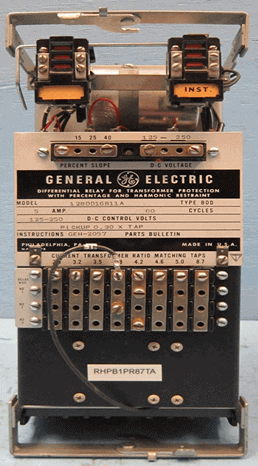
Figure 1 – Electromechanical protection relay
Nowadays electronic (solid-state) and microprocessor-based protection relays are commonly used in electrical utilities.
Electronic relays have only one protection function and different relays shall be used for different functions.
Microprocessor-based relays have many features available such as protection, control and monitoring.
Intelligent Electronic Devices (IED)
Microprocessor-based relays are known as Intelligent Electronic Devices (IED), which can provide 5-12 protection functions, 5-8 control functions controlling separate devices, an autoreclose function, self monitoring function and communication functions, being main their features:
- Many functions in a single relay
- Group settings readily changeable for changes in feeder configuration
- Programmable output relays
- Communication ports for connection to SCADA – Supervisory Control and Data Acquisition (Systems, Modems, and Personal Computers)
- Sequence-of-events stored for many recent faults
- Oscillography or waveform capture — storage of pre and post-fault current and voltage waveform data for analysis of faults
- Measurements
- Interlocking
- Aid to circuit breaker maintenance. Fault interrupting duty, per phase, can be recorded
- Fault Locater — Displays distance to fault
In the Figure 2 is possible to see an example of an IED.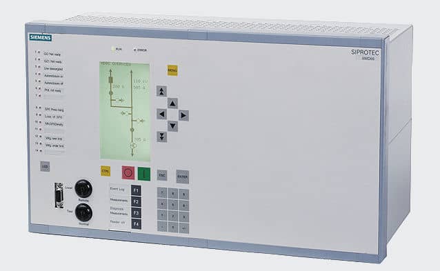
Figure 2 – IED
Functions and complexity of IED must be defined according to equipment to be protected, the networks characteristics and complementary actions required.
Actual IED are designed to fulfil the requirements of IEC[2] Standard 61850, which communication protocol is used. This standard was specifically developed for substation automation and provides interoperability and advanced communications capabilities.
The growth in the number of protection, control and monitoring points results a significant increase in the volume of substation data.
This data is usually primitive and stored in a digital form. It has to be processed and analyzed before any user is able to utilize the benefit of it.
In conventional protection system data and control signal from the relay are sent via an RTU (Remote Terminal Unit) to the SCADA system.
Extensive and costly cables may be required between various bays in the substation and the control room.
In modern protection system utilizing an IED relay the interconnection wiring between transducers and meters is no longer required.
The data and control signals from the IED relay are sent directly to the SCADA system via the high-speed dedicated communication network. The volume of data increases drastically when an IED is used as the control element and data source.
To provide the necessary connectivity between the various components of the system, a data network LONWORKS Local Operating Network (LON) is utilized.
IEC Standard 61850 defines the required protocols for communication, which can run over TCP/IP networks or substation LAN using high speed switched Ethernet to obtain the necessary response times below four milliseconds for protective relaying.
Protection Relays and Codes
In MV and HV substations, equipments, switchgears and power plants the more usual protection relays are indicated below, and between brackets is shown their code in accordance with IEEE/ANSI[3]/IEC Standards:
- Bearing protection (38)
- Breaker failure protection (50 BF)
- Bus bar differential protection (87B)
- Directional earth overcurrent (67N/67G)
- Directional phase overcurrent (67)
- Instantaneous earth overcurrent (50N/50G)
- Instantaneous phase overcurrent (50)
- Loss of field/excitation protection (40)
- Loss of phase (48)
- Over-excitation protection (24)
- Overfrequency and underfrequency (81)
- Overhead line differential protection (87L)
- Overhead line distance protection (21)
- Overload protection (49)
- Overspeed protection (12)
- Overvoltage (59)
- Restricted earth fault (64G/64REF)
- Reverse power protection (32)
- Time delay earth overcurrent (51N/51G)
- Time delay phase overcurrent (51)
- Transformer differential protection (87P)
- Undervoltage (27)
- Weak end infeed (21WI)
- Wrong phase sequence protection (47)
Mainly in HV overhead lines, HV power transformers and MV power transformers with rated power above 3-4 MVA, in order to increase system reliability and safety, is a common practice to use two sets of protections – one “main protection” and one “back-up protection”.
Protection with Fuses
A fuse is a type of low resistance resistor that acts as a “sacrificial device” to provide overcurrent protection that is still used in some LV and MV installations.
Its essential component is a metal wire or strip that melts when too much current flows, which interrupts the circuit, so that further damage by overheating or fire is prevented.
The metal strip or wire as a small cross-section compared to the circuit conductors and is enclosed by a non-combustible housing (casing).
The fuse element is made of zinc, copper, silver, aluminum or alloys to provide stable and predictable characteristics.
Casing may be of ceramic, glass, plastic, fiberglass, molded mica laminates or molded compressed fiber depending on manufacturer, application and voltage class.
Fuses are mounted on fuse holders, specifically designed for each type or family of fuses and rated voltages such as HRC fuse.
Examples of fuses and holders are shown in Figures 3 and 4.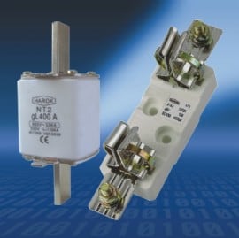
Figure 3 – LV NH type fuse and holder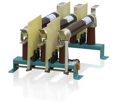
Figure 4 – MV fuses and holder
Main electrical characteristics of fuses are:
- Rated voltage
- Rated current (In): maximum current that the fuse can continuously conduct without interrupting the circuit.
- Breaking capacity (I1): maximum prospective current that the fuse can interrupt. It is the maximum fuse test value. This current is very high, generally between 20 kA and 63 kA.
- Minimum interrupting current (If): minimum current that can blow and interrupt the fuse
- Conventional non-fusing current (Inf): Value of current specified as that which the fuse-link is capable of carrying for a specified time (conventional time) without melting, expressed as a multiple of In (e.g. Inf = 1.25xIn)
- Nominal melting (I2t): measure of the energy required to melt the fusing element (based on Joule law) and is a value that is constant for each different fusing element.
- Time-current curve: shows the actuation time of the fuse (speed) as a function of the current (is usually indicated by manufactures, according to the standards)
Figure 5 shows an example of a time-current curve.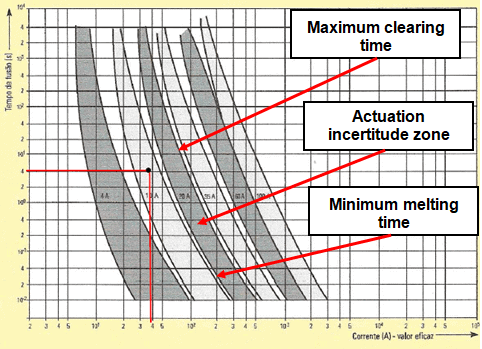
Figure 5 – Fuses time-current curve
Ambient temperature will change a fuse’s operational parameters and a temperature derating is necessary.
As an example a fuse rated for 1 A at 25 ºC may conduct up to 10% or 20% more current at -40 ºC and may open at 80% of its rated value at 100 ºC.
Operating values will vary with each fuse family and are provided in manufacturer data sheets.
The main selecting factors for a fuse are:
- Normal operating current
- Rated voltage (AC or DC)
- Ambient temperature
- Overload current and length of time in which the fuse must open
- Maximum available fault current
- Pulses, surge currents, inrush currents, start-up currents, and circuit transients
- Physical size limitations, such as length, diameter, or height
- Fuse features (mounting type/form factor, ease of removal, axial leads, visual indication, etc.)
- Fuse holder features, if applicable and associated rerating
- Application
- National wiring regulations and standards
French Standard NF EN 60269 classify fuses according to time-curves, functions and applications.This classification, largely used on many countries, is:
- gL/gG
- Functions
- Protection of cables and electrical devices. Discrimination ensured between two fuses or which there is a margin of two current ratings (e.g. 160 A and 100 A)
- Applications
- Protection at all levels of electrical power distribution in industries and residential home against overloads and short circuits. Main switchboard, feeder switchboards, main cubicles.
- aM
- Functions
- Direct protection of motors, must operate in conjunction with an external protection device (thermal relay). Easy discrimination with the gG fuses positioned upstream. Discrimination ensured between two fuses where there is a margin of two current rating (e.g. 160 A and 100 A)
- Applications
- Protection of low voltage motors.
- gR
- Functions
- Ultra fast protection fuse for semi conductors, very current limiting, low l2xt
- Applications
- Power semi conductor protection of soft starters, static relays, uninterruptible power supplies (UPS), variable speed drives, frequency
When an installation is protected by fuses, switch-disconnectors upstream of fuses must be used for safety reasons, to assure the isolation of the installation prior to replace a fuse or perform some maintenance works.
With a protection only with fuses is used, only phase overcurrents will be detected, and it is necessary to foreseen protection relays for other faults. For leakage current or ground fault current, GFCI (Ground Fault Circuit Interrupter) then used.
In this situation switches must equipped with an opening coil, which will be also actuated by the internal protection of the equipments.
Another precaution is that fuses must be provided with a mechanical device (striker pin) that will cause the switch to open, if only one fuse will act, to assure the total disconnection of the installation in fault.
Fuses shall also be provided with a coloured disc that falls out when the element is blown or an element window, built into the fuse body to provide visual indication of a blown element.
Grading and Protection Coordination
Introduction to Grading and Protection
When defining set-points of protection relays or rated current of fuses and LV circuit breakers (Such as ACB (Air Circuit Breaker)) it must be assured that the chosen values are suitable for the protection of the equipment and that the circuit breaker that trips or the fuse that will blow is only the one associated to the faulty circuit and not other protective devices, what could cause serious disturbances in the network and in quality and continuity of service.
To achieve this objective a grading and protection coordination study is required.
Basic Principles
Protection relay coordination studies are undertaken, to determine protection relay settings.
Fault levels have to be determined for all possible system operating conditions, this being used to determine the protection relays ability to detect and clear system faults.
The protection schemes are set to so as to isolate the least amount of the electrical system as possible, thus minimizing the disruption caused by the fault.
The protection relay clearance times are determined to meet primary plant short time rating, systems stability requirements and statutory authority requirements. We take care to determine the correct protection relay operating margins, both in current and time, so as to effectively eliminate malgrading.
When setting distance relays on double circuit high voltage feeders the zero sequence mutual coupling between the circuits is taken into consideration so as to minimize the possibility of over or under reaching occurring.
Relay operating characteristics and their setting must be carefully coordinated in order to achieve selectivity.
The aim is basically to switch off only the faulted component and to leave the rest of the power system in service in order to minimize supply interruptions and to assure stability.
Selectivity, or discrimination, between protection devices can be defined as “the coordination of the protection devices, in order for a fault that occurs at any point in the network to be eliminated by the upstream protection device, the protection device that is immediately upstream of the fault and by that protection device alone”.
Let us see an example of this definition looking the single line diagram of Figure 6, where there are protections systems SP1 to SP6: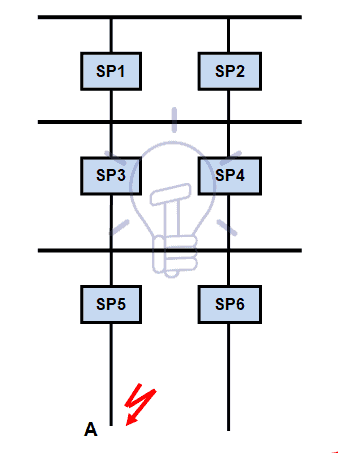
Figure 6 – Electrical installation single line diagram
Selectivity means that if a fault occurs at point A, the only protection system that should actuate is SP5 and that the other protection systems must not actuate.
Two principles are used to establish selectivity:
- Current discrimination.
- Time discrimination.
Grading and Protection Coordination in LV, MV and HV Networks
To establish grading and protection coordination studies it must be taken into account the configuration and the complexity of the network.
LV distribution and users networks have usually a radial configuration.
MV distribution networks have usually a combination of both radial and double-end feed with NO point configurations and an important complexity.
Users MV networks have usually a radial configuration, although in major plants a double-end feed with NO point configuration is used.
Due to the complexity of the networks grading and protection coordination studies for HV transmission networks and MV distribution networks, specialized engineers are required and the use of particular software tools for network analysis like ETAP, PSS/E, EPSO and PTW.
Grading and protection coordination studies of MV users’ network are usually easier and may follow the basic instructions that will be discussed later in this Section.
A particular attention must be observed in the boundary of electric distribution company network (infeeding) and users’ network and protection coordination protocol must be established between both entities.
For LV networks, using circuit breakers and/or fuses the selectivity of “circuit breaker/circuit breaker”, “fuse/fuse” and “circuit breaker/fuse” may be done by comparing “time-current curves” for a certain value of the fault current, using the principles of “current discrimination” and “time discrimination”, referred above.
Current discrimination is used for protection against overloads and the protection is selective if the ratio between the setting thresholds is higher than 1.6.
Time discrimination is used for the protection against short-circuits, using an upstream circuit breaker or fuse with a time delay and so tripping of the downstream device is faster; the protection is selective if the ratio between the short-circuit protection thresholds is no less than 1.5.
Cables Feeder Protection
You may read the updated post in details under the title of Cables Feeder Protection – Faults Types, Causes & Differential Protection.
Transformer Faults & Protection
As it is a very important and descriptive topic which should be discussed in very details, Hence, We have updated as well as merged the post here at Power Transformer Protection & Faults.
Overhead Lines Faults & Protection
For better user navigation, we have moved and updated this post here under the name of “Overhead Lines Faults & Protection“
Motor Projection
We have moved the blog post to a new link for better navigation and understanding. You can see it here @ motor protection, common types of motor faults and devices used for HV and LV Motor protection in the that post.
Generator Projection
We have already discussed the generator protection, common types of generator faults and devices used for generator protection in the previous post.
Miscellaneous Protection
Voltage and Frequency Protection
Load fluctuation and switching and power plants failures may cause variations on voltage and frequency of the network that can exceed the accepted limits of equipments and networks operation.
This situation can lead to damages on equipments and partial or total black-out in the network.
To avoid or to minimize this situation under and over voltage (codes 27 and 59, respectively) and frequency (codes 81U and 81O, respectively) protections shall be used.
Bus Bar Protection
In HV substations is common to install a bus bar protection relay, being the most used the differential protection (87B).
This relay is connected to all CT of the substation to evaluate the sum of incoming and outgoing currents, as shown in figure 25.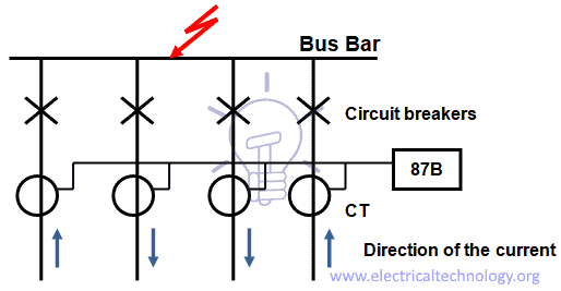
Figure 25 – Bus bar differential protection diagram
The operating principle of this protection is based on Kirchhof laws – current law.
The bus protection CT must be located on the feeder side of the breakers. If the bus protection CT are located on the bus side of the breaker, then a protection blind spot exists.
By using High Impedance relays in differential protection the system can be designed to be more tolerant of a saturated CT.
A non-linear resistor is connected across the relay terminals to limit the voltage across the differential relay to a safe value during fault conditions.
High impedance relays are used extensively in modern differential protection for high voltage buses.
The advantage of using High Impedance relays in bus differential protections is that they can be designed to remain stable (not operate) for external faults, when any one of the CT has saturated.
For an external fault, the worst case is with one CT completely saturated and the other CT not saturated. The resulting differential current will cause the maximum voltage to occur across the differential relay. A relay setting (in volts) is chosen, with sufficient margin, to ensure that the differential protection does not operate for this external fault condition.
The resistance of the CT secondary windings and cabling must be known, and is used in the relay setting calculations.
For internal faults the high impedance of the differential relay forces much of the resulting differential current through the CT exciting impedances. The resulting voltage developed across the relay is essentially the open-circuit voltage of the CT, and will be well above the voltage setting of the relay. A non-linear resistor or varistor is connected across the relay terminals to limit the voltage to a safe value during fault conditions.
When a bus fault is detected, all of the circuit breakers on that bus are tripped. Bus faults are almost always permanent, rather than transient faults.
There must therefore be no auto-reclosing of breakers after a bus fault. Bus protections will often cancel the auto-reclose on any breaker which may have been initiated by another protection.
Many substations use bus bar arrangements such as double bus bar, as shown in the Figure 26, where feeders can be switched from one bus to another by means of isolating switches.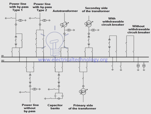
Figure 26 – Double bus bar arrangement
This complicates the bus protection somewhat, because the CT secondary circuits must be switched, by means of the isolator auxiliary switches, to correspond with the appropriate bus.
It is usual to have one zone of protection for each section of the bus. These are known as discriminating zones.
There is also another zone of differential protection for the entire substation, which is known as the check zone.
For tripping of a bus to take place with this arrangement it is necessary for both a discriminating zone relay and the check zone relay to operate.
Breaker Failure Protection
In HV substations is common the use of breaker failure protection (50BF), if a breaker fails to be triggered by a tripping order, as detected by the non-extinction of the fault current, this back-up protection sends a tripping command to the upstream or adjacent breakers.
The breaker failure protection function is activated by a 0/1 binary signal received from the overcurrent protection functions (50/51, 50N/51N, 46, 67N, 67). It checks for the disappearance of current during the time interval specified by the time delay T.
It may also be taken into account the position of the circuit breaker, read on the logic inputs to determine the actual opening of the breaker. Wiring a volt-free closed circuit breaker position contact on the breaker closed equation editor input can ensure that the protection is effective in the following situations:
- When 50BF is activated by protection function 50N/51N (set point Is0 < 0.2 In), detection of the 50BF current set point can possibly be not operational.
- When trip circuit supervision (TCS) is used, the closed circuit breaker contact is short-circuited.
Automatic activation of this protection function requires the use of the program logic circuit breaker control function. A specific input may also be used to activate the protection from the equation editor. That option is useful for adding special cases of activation (e.g. tripping by an external protection unit).
The time-delayed output of the protection unit should be assigned to a logic output via the control matrix.
The starting and stopping of the time delay T counter are conditioned by the presence of a current above the set point (I > Is).
Weak End Infeed
Weak end infeed protection is a complement to the distance protection that is used if the value of fault current in the overhead line is lower than the set-point regulation of the distance protection.
Capacitor Banks Protection
When it comes to Power factor, Each phase of a capacitor bank is formed by groups of capacitors in series association for power factor improvement. The 3 phases are then connected in star, being the neutral point isolated or grounded, according to the operation of the network, as shown in Figure 27.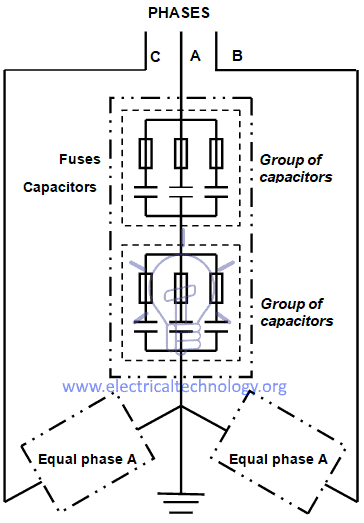
Figure 27 – Diagram of a capacitor bank
Common capacitor banks faults are:
- Capacitors short-circuit or fault in the connection cables.
- Short-circuit between the units and the metallic structure of racks or switchboards (phase-to-earth fault).
- Overloads caused by network harmonics.
- Dielectric breakdown due to network overvoltages or lightning.
When a group of capacitors fail and the neutral is grounded the bank will be imbalanced and a current will circulate in the neutral.
Each capacitor or group of capacitors is usually protected by fuses, which are already installed by the manufacturer.
Fuses must have an I2t characteristic that will not cause the fuse to blow with the inrush current resulting from the connection of the capacitor bank.
Common protection devices of capacitor banks are:
- Instantaneous phase overcurrent (50)
- Instantaneous earth overcurrent (50N/50G)
- Time delay phase overcurrent (51)
- Time delay earth overcurrent (51N/51G)
- Over voltage protection (49)
[1] HV: High Voltage (V ≥ 60 kV); MV: Medium Voltage (1 kV < V < 60 kV); LV: Low Voltage (V ≤ 1 kV). [2] IEC: International Electrotecnical Comission. [3] IEEE: Institute of Electrical and Electronics Engineers. ANSI: American National Standards Institute. [4] Residual capacitive current in the case of phase-to-earth fault (IC) is calculated by the equation IC = 3XcU, where Xc is the capacitive reactance of the cable and U the phase-to-phase voltage of the network. [5] In this article Gas Insulated Transformers (GIT) are not analasyzed. [6] rms: root mean square. [7] Prime mover is the component that is used to drive the generator and may be combustion engines (the case of diesel generator sets), gas turbines, steam turbines, wind turbines and hydraulic turbines. [8] The field in an AC generator consists of coils of conductors within the generator that receive a voltage from a source (called excitation) and produce a magnetic flux. The magnetic flux in the field cuts the armature to produce a voltage. This voltage is ultimately the output voltage of the generator.
![]()


this is nice and good i have enjoyed