Parameters of a Solar Cell and Characteristics of a PV Panel
Parameters and Characteristics of a Photovoltaic Cell
What exactly is a Solar Photovoltaic Cell?
A solar cell is a semiconductor device that can convert solar radiation into electricity. Its ability to convert sunlight into electricity without an intermediate conversion makes it unique to harness the available solar energy into useful electricity. That is why they are called Solar Photovoltaic cells. Fig. 1 shows a typical solar cell.

Various factors govern the electricity generated by a solar cell such as;
- The intensity of the light: Higher sunlight falling on the cell, more is the electricity generated by the cell.
- Cell Area: By increasing the area of the cell, the generated current by the cell also increases.
- The angle of incident: If the light falling on the cell is perpendicular to its surface, the power generated by it is optimum. Ideally, the angle should be 90o but practically it should be as close as 90o.
The solar cell is a two-terminal device. One is positive (anode) and the other is negative (cathode). A solar cell arrangement is known as solar module or solar panel where solar panel arrangement is known as photovoltaic array.
- Related Post: How to Design and Install a Solar PV System?
Working of a Solar Cell
The sunlight is a group of photons having a finite amount of energy. For the generation of electricity by the cell, it must absorb the energy of the photon. The absorption depends on the energy of the photon and the band-gap energy of the solar semiconductor material and it is expressed in electron-volt (eV).
The photons are absorbed by the semiconductor material which results in the generation of electron-hole pairs, where electrons are negative charge and holes are positive charge. When a load is connected there is a separation of electrons and holes at the junction, the holes move towards the anode side and the electrons towards the cathode side.
Thus, the separation of these two charges creates an electric potential difference and we get a voltage across the cell’s terminal. This voltage is used to drive the current in the circuit.
Related Post: A Complete Guide About Solar Panel Installation. Step by Step Procedure with Calculation & Diagrams
Solar Cell Parameters
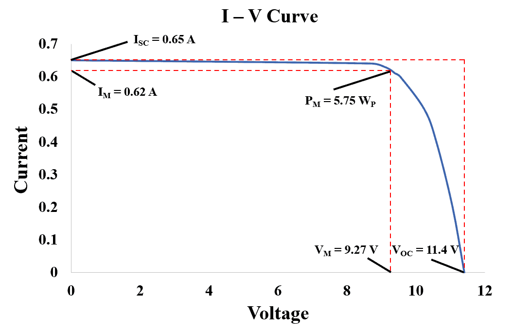
The conversion of sunlight into electricity is determined by various parameters of a solar cell. To understand these parameters, we need to take a look at the I – V Curve as shown in figure 2 below. The curve has been plotted based on the data in table 1.
Table 1
| Amps | Volts | Watts |
| 0 | VOC = 11.4 | 0 |
| 0.2 | 11.06 | 2.21 |
| 0.4 | 10.59 | 4.24 |
| 0.5 | 10.24 | 5.12 |
| 0.6 | 9.54 | 5.72 |
| 0.61 | 9.39 | 5.73 |
| IM = 0.62 | VM = 9.27 | PM = 5.75 |
| 0.63 | 9.08 | 5.72 |
| 0.64 | 8.72 | 5.58 |
| ISC = 0.65 | 0 | 0 |
The cell parameters are given by manufacturers at the STC (Standard Test Condition). Under STC the corresponding solar radiation is equal to 1000 W/m2 and the cell operating temperature is equal to 25oC. The solar cell parameters are as follows;
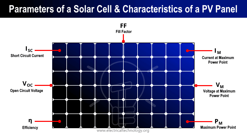
Short Circuit Current (ISC):
Short circuit current is the maximum current produced by the solar cell, it is measured in ampere (A) or milli-ampere (mA). As can be seen from table 1 and figure 2 that the open-circuit voltage is zero when the cell is producing maximum current (ISC = 0.65 A).
The value of short circuit depends on cell area, solar radiation on falling on cell, cell technology, etc. Sometimes the manufacturers give the current density rather than the value of the current. The current density is denoted by “J” and the short circuit current density is denoted by “JSC”. The short circuit current density is obtained by dividing the short circuit current by the area of the solar cells as follow:
JSC = ISC / A
Let’s take an example, a solar cell has a current density of 40 mA/cm2 at STC and an area of 200 cm2. Then the short circuit current can be determined as follows;
ISC = Jsc × Area = 40 mA/cm2 × 200 cm2 = 8000 mA = 8 A
Open Circuit Voltage (VOC):
Open circuit voltage is the maximum voltage that the cell can produce under open-circuit conditions. It is measured in volt (V) or milli-volt (mV). As can be seen from table 1 and figure 2 that the short circuit current is equal to zero when the cell produces maximum voltage. The value of VOC depends on cell technology and the operating temperature of the cell.
Maximum Power Point (PM):
Maximum power point represents the maximum power that a solar cell can produce at the STC (i.e. solar radiance of 1000 W/m2 and cell operating temperature of 25oC). It is measured in WPeak or simply WP. Other than STC the solar cell has PM at different values of radiance and cell operating temperature.
The cell can operate at different current and voltage combinations. But it can only produce maximum power PM at a particular voltage and current combination. As shown in figure 2 the maximum power point is at the knee of the I – V curve and is the product of IM and V
PM = IM × VM = 0.62 × 9.27 = 5.75 WP
Current at Maximum Power Point (IM):
It represents the current which the solar cell will produce when operating at the maximum PowerPoint. It is denoted by IM and can be seen in figure 2 that its value is always less than the short circuit current (ISC). It is measured in ampere (A) or milli-ampere (mA).
The Voltage at Maximum Power Point (VM):
It represents the voltage that the solar cell will produce when operating at the maximum PowerPoint. It is denoted by VM and can be seen in figure 2 that its value is always less than the open-circuit voltage (VOC). It is measured in volts (V) or millivolts (mV).
Fill Factor (FF):
It represents the area covered by IM – VM rectangle with the area covered by ISC – VOC rectangle as by dotted lines in figure 2. The fill factor represents the squareness of the I – V curve. It is represented in terms of the percentage (%), the higher the fill factor in percent the better is the cell.
FF = PM / (ISC ×VOC)
Based on the data in table 1 and figure 2 we can determine the fill factor as follows;
FF = [5.75 / (0.65 × 11.4)] × 100 = 77.59 %
Represented in percentage by multiplying it by 100.
Efficiency (ƞ):
- A solar cell efficiency is defined as the maximum output power (PM) divided by the input power (PIN). It is measured in percentage (%), which indicates that this percentage of input sunlight power is converted to electrical power. The input power is power density. Therefore, to calculate efficiency multiply PIN at STC by area. The efficiency can be calculated as follows;
ƞ = PM / (PIN × Area)
If the given area of the cell is 0.01 m2, PM = 5.75 WP then the efficiency at standard test condition can be given as;
ƞ = [5.75 WP / (1000 W/m2 × 0.01 m2)] = 57.5 %
Represented in percentage by multiplying it by 100.
Photovoltaic Technologies
A wide variety of solar cells are available in the market, the name of the solar cell technology depends on the material used in that technology. Hence different cells have different cell parameters like short circuit current density, efficiency, open-circuit voltage, fill factor, etc. The following table 2 shows the list of commercially available cells and their parameters value range.
Table 2
| Cell Type | Efficiency (%) | Open Circuit voltage (V) | Current Density (mA/cm2) | Cell Area (cm2) | Fill Factor (FF) |
| Mono-crystalline silicon | 14 – 17 | 0.55 – 0.68 | 30 – 38 | 5 – 156 | 70 – 78 |
| Multi-crystalline silicon | 14 – 16 | 0.55 – 0.65 | 30 – 35 | 5 – 156 | 70 – 76 |
| Amorphous Si | 6 – 9 | 0.70 – 1.1 | 8 – 15 | 5 – 200 | 60 – 70 |
| Cadmium telluride | 8 – 11 | 0.80 – 1.0 | 15 – 25 | 5 – 200 | 60 – 70 |
| Copper-indium-gallium-selenide | 8 – 11 | 0.50 – 0.7 | 20 – 30 | 5 – 200 | 60 – 70 |
| Gallium arsenide | 30 – 35 | 1.0 – 2.5 | 15 – 35 | 1 – 4 | 70 – 85 |
Factors affecting the Power Generated by Solar Cells
Conversion Efficiency (ƞ):
Not all the light falling on the solar cell is converted into electrical energy. Conversion efficiency is referred to as the ratio of electrical energy generated to the input light energy. We cannot change the efficiency of the cell, based on the manufacturing process and the material used in it and its value remains fixed.
Solar cell maximum power PM depends upon the voltage that it develops across the cell terminal and the current it can supply. The cell area is one of the important factors that affect the output power developed by the cell. The value of the output power can be determined for a given input power in (W/m2), cell’s conversion efficiency in (%), and area of the cell in (m2).
The solar cell efficiency is given under STC and the input power (PIN) is taken as 1000 W/m2. Thus, by using the formula given below we can determine the output power generated for different efficiencies.
PM = (PIN × Area) × ƞ
Let’s say we have to calculate the output power at STC having efficiencies 30% and 25% and an area of 0.01 m2. Thus, for 30% efficiency we get;
PM = (1000 W/m2 × 0.01 m2) × 0.30 = 3 WP
And for 25% efficiency we get;
PM = (1000 W/m2 × 0.01 m2) × 0.25 = 2.5 WP
Amount of Input Light:
The intensity of light falling on the cell keeps on changing throughout the day. Depending on the light falling on the cell the current and voltage of the cell changes. The current generated by the cell is directly dependent on the light falling on it.
Form morning till afternoon the light falling on the cell increases, hence the current generated by the cell also increases. From afternoon till sunset the light falling on the cell decreases, hence the current generated by the cell also decreases. There is no major variation in the output voltage of the cell as it is not affected by the variation in sunlight.
Let’s say we have to calculate output power for a cell having an area of 0.01 m2 for an input power of 1000 W/m2 and 800 W/m2 having an efficiency of 25%. Thus, for an input power of 1000 W/m2 we get the output power as follows;
PM = (1000 W/m2 × 0.01 m2) × 0.25 = 2.5 WP
And for an input power of 800 W/m2;
PM = (800 W/m2 × 0.01 m2) × 0.25 = 2 WP
As we can see there is a decrease in the output power due to a decrease in the input power. Thus, the amount of power generated by the cell is proportional to the sunlight.
Related Post Types of Solar Panels and Which Solar Panel Type is Best?
Cell Area:
The short circuit current of the solar cell depends on the area of the cell. The output current is directly proportional to the cell area. Larger the cell area the amount of generated current is also large and vice versa. For example, a 200 cm2 area will produce 2 A current and a 200 cm2 will produce 4 A current for the same irradiance of 1000 W/m2.
As we saw before that the current density is obtained by dividing the current by the area of the cell. The current density (JSC) is fixed for a given sunlight intensity and it does not depend on the area. Let’s take an example where we have to calculate the output current of the solar cell having an area of 20 cm2 and 50 cm2.
Having a constant current density of 35 mA/m2. The output current for 20 cm2 can be calculated as follows;
ISC = JSC × Area = 35 mA/m2 × 20 cm2 = 0.70 A
The output current for 50 cm2 can be calculated as follows;
ISC = JSC × Area = 35 mA/m2 × 50 cm2 = 1.75 A
Thus, from the above calculation, it is clear that the larger the cell area higher is the value of current and smaller the cell area lower is the value of the current.
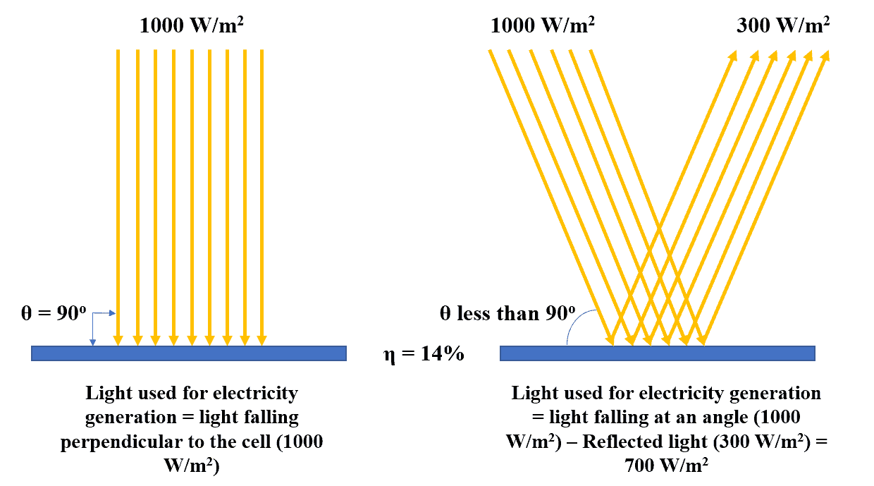
The Angle of Light (θ):
The solar cell produces maximum output power for given sunlight when the angle of the light and the cell are perpendicular to each other (i.e. 90o) as shown in figure 3. When the angle of the incident of light is less than or greater than 90o as shown in figure 3 than it will produce output power lower than the maximum output power capability of the cell.
When the light falls on an angle greater or lesser than 90o some part of the light is reflected, and the light utilized by the cell less than the actual falling on it. This results in a reduction of the output power generated by the cell. It is due to this reason that we must install the solar cell at an angle perpendicular to the falling light to generate maximum possible electricity.
Operating Temperature (T):
The manufacturers provide the cell voltage, current and power rating at the STC having irradiance of 1000 W/m2 and temperature of 25o But in practice, the solar cell temperature varies due to ambient temperature and further the cells are enclosed in glass due to which the temperature of the solar cell further increases.
This change in temperature affects the voltage, power, and efficiency of the cell, the rise in the cell temperature above the STC reduces the output of these parameters. The decrease in these parameters differs for different solar cells available in the market.
Let’s take an example to understand the decrease in one of the parameters (i.e. voltage). A cell is having an output voltage of 0.9 V at STC. The operating temperature of the cell is 50o C. The output voltage of the cell decreases by 2.1 mV/o C. what can be the new value of the output voltage?
ΔT = Tactual – Tstandard = 50 – 25 = 25oC
The reduced output voltage = Open circuit voltage (VOC) at STC – (Decrease in voltage – ΔT) = 0.9 – (2.1 × 10 -3 × 25) = 0.84 V
From the above calculation, it can be concluded that there is a decrease in the output voltage if the temperature rises above STC (i.e. above 25oC).
Related Posts:
- Series Connection of Solar Panel with Auto UPS System
- Parallel Connection of Batteries with Solar Panel
Conclusion
It is due to development in the semi-conductor technology that we can convert abundant solar light into electricity. In this article we studied the working of the solar cell, different types of cells, it’s various parameters like open-circuit voltage, short-circuit current, etc. that helps us understand the characteristics of the cell. The factors affecting the power generated by the cell were also studied including power conversion efficiency, amount of input light, cell area, etc. that affects the performance and helps us understand the behavior of the cell under a different scenario. With the understanding of solar cell technology, we can utilize it in the best possible way to fulfil our day to day energy requirements.
Related Posts: