Introduction of Custom Power Devices For Power Quality Improvement
Power Quality Improvement using DSTATCOM, DVR & UPQC Devices
Introduction
Power distribution systems, ideally, should provide their customers with an uninterrupted flow of energy at smooth sinusoidal voltage at the contracted magnitude level and frequency however, in practice, power systems, especially the distribution systems have numerous nonlinear loads, which significantly affect the quality of power supplies.
As a result of the nonlinear loads, the purity of the waveform of supplies is lost. This ends up producing many power quality problems. Power quality phenomenon or power quality disturbance can be defined as the deviation of the voltage and the current from its ideal waveform.
In electrical power system, voltage control performs an essential function to ensure the voltage interruptions like sag, swell and harmonics can be minimized and then increase the power quality, reliability and availability. According to IEC (International Electro-technical commissions) the voltage standard should be in the range of ±6% of the specified value of voltage.
To mitigate all the power quality problems number of power devices are used in power system.
Custom Power Devices
The Classification of custom power devices can be done into two major categories, one is network configuring type and the other is compensating type.
The network configuring type devices changes the configuration of the power system network for power quality enhancement. SSCL (Solid State Current Limiter), SSCB (Solid State Circuit Breaker) and SSTS (Solid State Transfer Switch) are the most representative in this category.
The compensating type devices are used for active filtering; load balancing, power factor correction and voltage regulation. Compensating devices include DSTATCOM (Distribution Static Compensator), DVR (Dynamic Voltage Restorer) and Unified Power Quality Conditioner (UPQC).
In the power system, nonlinear loads results in production of harmonics due to which load current waveform gets distorted. The power-quality problems include voltage sags/swells, load voltage harmonic distortions, and unbalancing.
- DSTATCOM (Distribution Static Compensator) is a compensating device which is used to control the flow of reactive power in the distribution systems and minimize current related problems in system and it connect parallel with grid for operation.
- DVR (Dynamic Voltage Restorer) is compensating device used to detects and compensates all the voltage related problems in power system and it connect in series with grid for operation.
- UPQC (Unified Power Quality Conditioner) is combination of both DVR and DSTATCOM, which is used to maintain all current and voltage related problem and improve power quality in power system.
These three devices called Active Power Filter.
- Active filters have the advantage of being able to compensate for harmonics without fundamental frequency reactive power concerns. Currently they are based on PWM converters and connect to low and medium voltage distribution system in shunt or in series.
- Series active power filters must operate in conjunction with shunt passive filters in order to compensate load current harmonics. Shunt active power filters operate as a controllable current source and series active power filters operates as a controllable voltage source.
- Both schemes are implemented preferable with voltage source PWM inverters, with a dc bus having a reactive element such as a capacitor. Active power filters can perform one or more of the functions required to compensate power systems and improving power quality. The rating of the active power can be less than a conquerable passive filter for the same nonlinear load and the active filter will not introduce system resonances that can move a harmonic problem from one frequency to another.
DSTATCOM – (Distribution Static Compensator)
Click image to enlarge

- The coupling of DSTATCOM is three phase, in parallel to network and load. It work as current sources, connected in parallel with the nonlinear load, generating the harmonic currents the load requires also balance them in addition to providing reactive power.
- The performance of the DSTATCOM depends on the control algorithm e. the extraction of the current components. For this purpose there are many control schemes which are reported in the literature and some of these are instantaneous reactive power (IRP) theory, instantaneous compensation, instantaneous symmetrical components, synchronous reference frame (SRF) theory, computation based on per phase basis, and scheme based on neural network. Among these control schemes instantaneous reactive power theory and synchronous rotating reference frame are most widely used.
- In order to compensate undesirable components of the load current the DSTATCOM injects currents into the point of common coupling. With an appropriated control strategy, it is also possible to correct power factor and unbalanced loads. This principle is applicable to any type of load considered a harmonic source.
- Its advantage is that it of carries only the compensation current plus a small amount of active fundamental current supplied to compensate for system loses.
DVR – (Dynamic Voltage Restorer)
Click image to enlarge
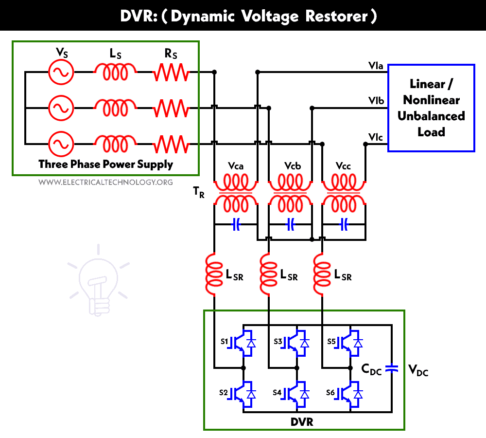
- The dynamic voltage restorer(DVR) detects and compensates for sags in the voltage of the AC power source so that the loads are insulated from these power reliability issues.
- The DVR consists of DC power sources, an IGBT converter, and an injection transformer which is connected in series with the power line and the sensitive load. The DC power sources that can be used are batteries, supercapacitors, superconducting magnetic storage units, and flywheels.
- A sag in the input AC power line voltage may propagate through the power network due to a fault in one of the distribution feeder lines. The DVR detects the sag and generates AC power from the DC power source by using the IGBT converter.
- The generated power is fed to the line by the transformer to correct the sag so that the sensitive load receives a highly reliable AC input power.
- DVR injects the difference between the pre-sag and the sag voltage, by supplying the real power requirement from the energy storage device together with the reactive power. The maximum injection capability of the DVR is limited by the ratings of the DC energy storage and the voltage injection transformer ratio.
- In the case of three single-phase DVRs the magnitude of the injected voltage can be controlled individually. The injected voltages are made synchronized (i.e. same frequency and the phase angle) with the network voltages.
UPQC – (Unified Power Quality Conditioner)
Click image to enlarge
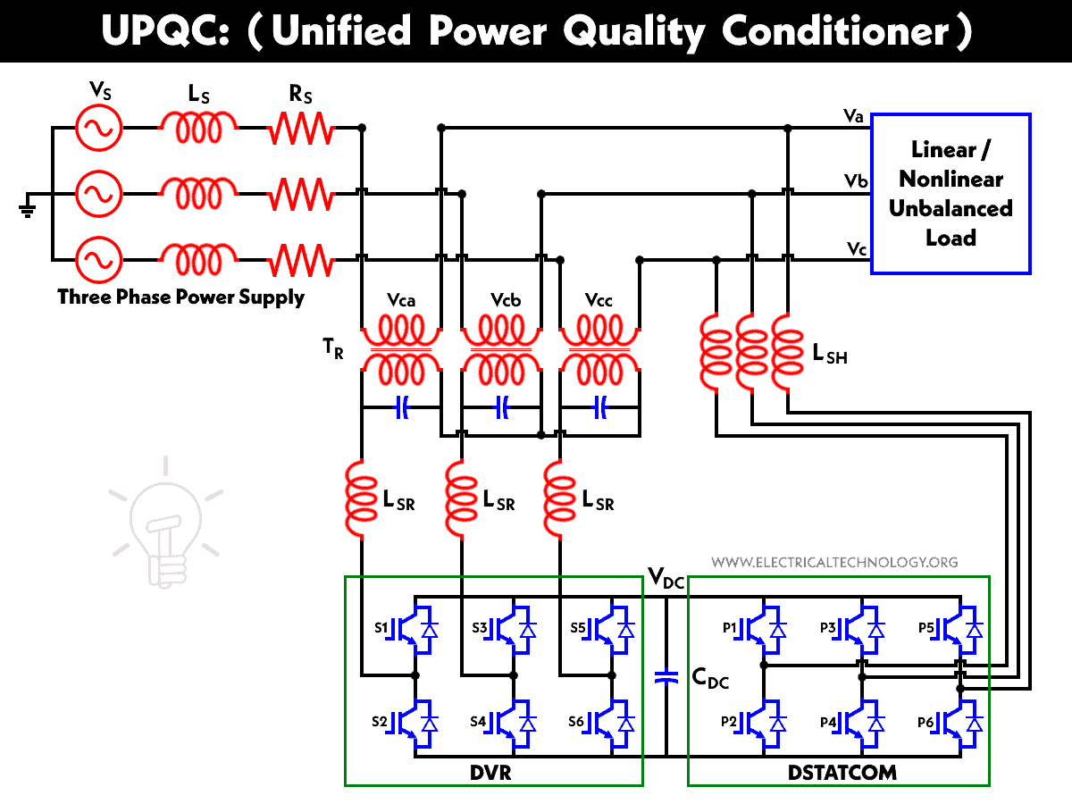
- The Unified Power Quality Conditioner is a custom power device that is employed in the distribution system to mitigate the disturbances that affect the performance of sensitive and/or critical load. It is a type of hybrid APF and is the only versatile device which can mitigate several power quality problems related with voltage and current simultaneously therefore is multi functioning devices that compensate various voltage disturbances of the power supply, to correct voltage fluctuations and to prevent harmonic load current from entering the power system.
- The best protection for sensitive loads from sources with inadequate quality is shunt-series connection i.e. unified power quality conditioner (UPQC). In utilizing the unified power quality conditioner to solve almost all power quality problems for example voltage sag, voltage swell, voltage outage and over correction of power factor and harmonics in the current and voltage.
- Unified Power Quality Conditioner (UPQC) for non-linear and a voltage sensitive load has following facilities:
- It eliminates the harmonics in the supply current, thus improves utility current quality for nonlinear loads.
- UPQC provides the VAR requirement of the load, so that the supply voltage and current are always in phase, therefore, no additional power factor correction equipment is necessary.
- UPQC maintains load end voltage at the rated value even in the presence of supply voltage sag.
- The voltage injected by UPQC to maintain the load end voltage at the desired value is taken from the same dc link, thus no additional dc link voltage support is required for the series compensator. The UPQC consists of two three phase inverters connected in cascade in such a manner that one of the inverter is connected in series with the supply voltage through a transformer and other inverter is connected in parallel with the load.
- The main purpose of the shunt compensator is to compensate for the reactive power demanded by the load, to eliminate the harmonics and to regulate the common dc link voltage. The series compensator is operated in PWM voltage controlled mode. Injects voltage in quadrature advance to the supply voltage (current) such that the load end voltage is always maintained at the desired value. The two inverters operate in a co-ordinate manner.
Related Posts:
- Load Frequency Control (LFC) & Turbine Governor Control (TGC) in Power System
- Analysis of Reactive Power in Power System
- Power Factor improvement Methods with their advantages & Disadvantages
- FACTS – Flexible AC Transmission System – Types of FACTS Controllers & Devices
- Types of Faults in Electrical Power System
- What is HVDC? – High Voltage Direct Current Power Transmission
- Types of HVDC Systems and MTDC Configurations
- Classification of Electric Power Distribution Network Systems
- Calculation & Design of Solar Photovoltaic Modules & Array
- Ferranti Effect – Causes, Circuit Diagram, Advantages & Disadvantages
- Skin Effect and Factors Affecting Skin Effect in Power Lines
- Corona Effect & Discharge in Transmission Lines & Power System