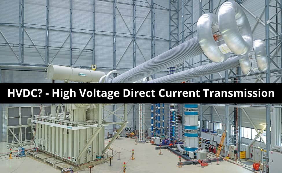
What is HVDC? – High Voltage Direct Current Power Transmission
High Voltage Direct Current Power Transmission – Components & Types of HVDC System
The power system network is classified into three parts; Power Generation, Transmission, and Distribution. The transmission system is used to connect the generating system with the load. High voltage is used to transmit the power to reduce transmission losses.
According to the type of transmitted power, the transmission lines are classified into two types.
- HVAC Transmission line
- HVDC Transmission line
The power is generated in form AC power and most of the load is designed to operate on AC power. Hence, in a conventional transmission system, the power is transmitted through the HVAC Transmission line. But there are several disadvantages. To overcome these disadvantages and emerging technology in power electronics, the HVDC transmission line is introduced.
- Related Post: Types of HVDC Systems and MTDC Configurations
What is HVDC?
HVDC is the acronym of High Voltage Direct Current or simply High Voltage DC. It is also known as electrical superhighway or power superhighway. HVDC is an effective way to transmit the vast amount of electrical power using DC (Direct Current) over long distance by overhead transmission lines, underground cables or submarine cables.
HVDC system is also used to interconnect separate power system networks having different characteristic and frequencies where AC transmission is not applicable. There are some advantages of HVDC over HVAC, that’s why it is preferred as compared to a typical HVAC system. Let’s see what is HVDC and how it works?
Good to know:
- The longest HVDC power transmission line in the world is 2385km in Madeira, Brazil.
- Recently in China, a 12GW power was transmitted at 11kV DC over a distance of 3300km.
Related Post: Differences Between HVAC and HVDC – Power Transmission
Components of HVDC Transmission Line
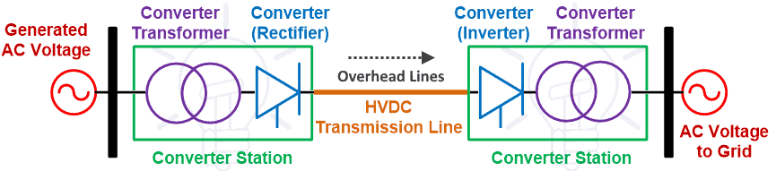
The below figure shows the single line diagram of the HVDC transmission line. Here we will discuss the function of each component.
The component used for this system is listed below.
- Converter Transformer
- Converters
- Filters
- Smoothing Reactor
- Earth Electrodes and Electrode Line
- DC Transmission Lines or Cables
- Reactive Power Source
- AC Switchgear
Related Post: Advantages of HVDC over HVAC Power Transmission

Converter Transformers
The converter transformer is different than the conventional transformer used in the HVAC transmission line. Because this transformer is connected with the power electronics equipment and designed to withstand DC voltage stress and harmonic currents. In the converter transformer, the harmonic content is higher compared to the conventional transformer. Hence, it causes more leakage flux and it forms local hotspot in the winding. So, these transformers require extra cooling arrangements to avoid the effect of a hotspot.
The step-up transformer is used to increase the voltage level at sending end and the step-down transformer is used to decrease the voltage level at receiving end of the line. There are different configurations according to the application i.e. two three-phase units or three single-phase units used.
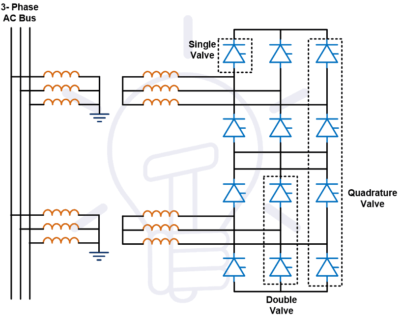
Converters
Electrical power generates and utilizes in the form of AC power. Hence, the converters are used in both ends of the transmission line. The rectifier is used to convert AC to DC at sending end of the line. And the inverter is used to convert DC to AC at receiving end of the line. The size of these converters is very big and generally, it is placed in a separate building known as valve hall.
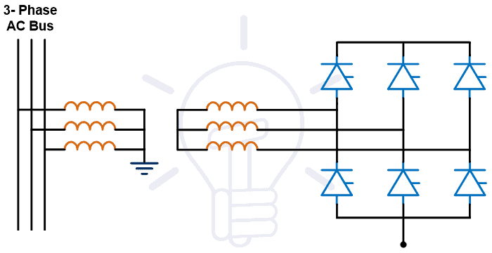
When the HVDC lines are introduced, the thyristors are used as a power electronics switch in converters. These converters are known as line commuted converters. In thyristor base converter, thyristor valves are grouped in pairs. Each converter consists of six or twelve valves. It requires voltage from the AC system for communication. But after that, the voltage source converters are introduced. This type of converter used IGBT (Insulated Gate Bipolar Transistor) instead of the thyristor. And this converter does not need AC voltage for communication.
Filters
The converters are used power electronics switches. The harmonics are produced due to switching in converters at both ends of a transmission line. These harmonics are transferred to the AC system. And that can be led to overheating of equipment. Therefore, it is necessary to reduce or eliminate harmonics. The filters are used to reduce harmonics.
These filters are used on both the AC side and DC side. The filter used in the AC system is known as the AC filter and the filter used in the DC system is known as the DC filter. It consists of series combinations of capacitors and inductors and tuned to eliminate the expected harmonic frequencies.
The AC filters provide low impedance and used passive components. AC filters provide the reactive power required for the operation of the converter. The DC filters small in size and less expensive compared to the AC filters. The intensity of harmonics is less in voltage source converters compared to the line commutated converters.
- Related Post: AC or DC – Which One is More Dangerous And Why?
Smoothing Reactor
Smoothing Reactor is connected in series with the converter at the DC side. It is used to make current ripple-free and decrease the harmonics in the DC system. It is also used for protection purposes by limiting the fault current. It can be connected on the line side or neutral side.
The smoothing reactors are also used to regulate the DC current. If a sudden change occurs in the DC current, it will oppose and allow the DC current to flow at a fixed value. Hence, it reduces stress on the converter valve by preventing sudden changes. The smoothing reactor is an oil-cooled reactor with high inductance.
Earth Electrodes and Electrode Line
The mid-point of the converter is earth through the earth electrode at both sides of the transmission line. These electrodes are placed at a far distance (5 to 20 km) from the substation. And the electrode line is used to make a connection with the earth electrodes. To reduce the galvanic corrosive the earth mat is also used.
DC Transmission Lines and Cables
According to the type of HVDC system, the number of conductors is selected. It is used to transmit the HVDC power from the sending end to the receiving end. In the DC system, there is no skin effect due to the absence of frequency. And compared to the HVAC system, the size of the conductor is small for the same power.
- Related Post: Overhead Lines Protection – Faults & Protection Devices
Reactive Power Source
Reactive power is required for the operation of the converter. This power can be supplied through the capacitor bank, synchronous condenser, or a suitable generating station locate near the converter. In the case of line commutated converter, the reactive power required is between 40-60% of its power rating. This demand can be reduced by converter transformer having a sufficient range of on-load tap changers. The harmonic filter supplies some amount of reactive power. In the case of voltage sourced converter, it can generate or absorb reactive or real power. Hence, it does not require an additional reactive power source.
AC Switchgear
The converter station consists of various protection equipment like a circuit breaker, grounding switch, isolating switch, and lighting arrester. The circuit breaker is used to protect the converts against overheating. The lightning arrester is used to protect the converter station from a lightning surge on the AC system. It also consists of an instrument transformer for measurement as well as control and protection purposes.
- Related Post: Difference between AC Drives and DC Drives
Types of HVDC Transmission Line
According to the arrangement of HVDC Cables, the transmission lines are classified into four types.
- Monopolar System
- Bipolar System
- Homopolar System
- Back-to-Back HVDC System
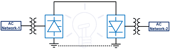
Monopolar System
In this type of HVDC system, only one conductor is used to make a connection between sending end and receiving end. And the ground or seawater is used for the return path. Hence, the cost of this system is less compared to other systems. But it is not useful for high power applications.
The positive or negative polarity is used to transmit power. Generally, negative polarity is used on overhead lines because the radio interference is lesser. The block diagram of this system is as shown in the below figure.
- Related Post: What Happens When an AC Line Touches a DC Line?
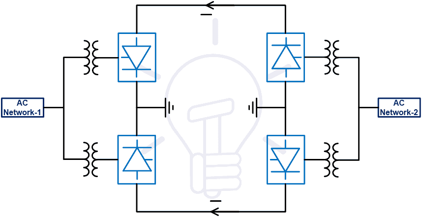
Bipolar HVDC System
This system is the most commonly used compared to other HVDC systems. In a bipolar HVDC system, two conductors are required. One conductor is a positive conductor and the other is a negative conductor of the same magnitude with respect to earth. Hence the voltage difference between each conductor is twice. This type of system arrangement is used to transmit power for long-distance.
Two converters are used at each end of the line. The neutral point is grounded. Therefore, each line can operate independently. Hence, it is a combination of two monopolar systems. If a fault occurs in one conductor, the second conductor will continuously transmit power and increase the reliability of the system. In this condition, the ground is used as a return path and it works as a monopolar system. When a fault is cleared, the system again works as a bipolar system.
In this type of system, normally the current is not flowing through the earth. But sometimes the balance current will flow through the earth. The circuit diagram of this system is as shown in the below figure.
Related Post: Why Do Electronic Circuits Use DC Current instead of AC?

Homopolar HVDC System
In this type of system, two or more conductors are used on the same tower. The polarity for all conductors is the same and most probably it is negative polarity. For return, path earth is used. In this type of system, corona loss and radio interference are very less.
If a fault occurs in one conductor, the second conductor will continue to transmit the power. In this condition, more than 50% of rated capacity power can transmit by overloading on a conductor. But it will increase the power loss. The main disadvantage of this system is the large return current. The block diagram of this system is as shown in the below figure.
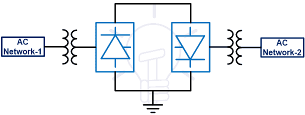
Back-to-back HVDC system
This system is also known as the HVDC coupling system. Because this system is used to connect two AC systems in the same location. Two back-to-back converters are connected at the same place. There is no transmission line. This system is used to make the asynchronous interconnection between two independently controlled AC networks. The block diagram of this system is as shown in the below figure.
- Related Post: SCADA Systems for Electrical Distribution
Economic Distance for HVDC Transmission
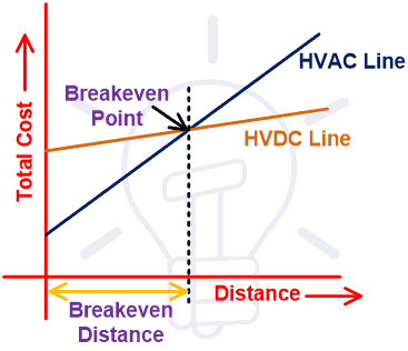
The cost of the HVDC Transmission line is less compared to the HVAC transmission line if the length of the line is more than the breakover distance. In this system, the converters are used at both ends of the line. And the cost of the converter is very high.
In the case of the HVAC Transmission system, after a certain length, substations are required and the intermediate compensating network is necessary for good power quality. In the case of the HVDC line, this type of component is not required. And the size of the tower is less in the HVDC system compared to the HVAC system. Therefore, the overall cost of this system is less.
But if the length of the line is small, then the converter cost is increased, and, in this condition, the HVDC system is not economical. So, for long-distance line HVDC line is economical and for a small distance of line HVAC system is economical.
The below graph shows the relation between the cost and length of the line for HVDC and HVAC systems. The point where both graphs intersect, that point is known as breakover point.
- Related Post: Why Does A Capacitor Block DC But Pass AC?
Advantages of HVDC Transmission Line
1) Number of Conductors
In the HVAC Transmission line, according to the type of system, several conductors will be 3, 4, or 6. But in the case of the HVDC transmission line, the power can be transmitted by only one conductor, and for bulk power transmission it needs only two conductors in a bipolar HVDC system. Therefore, it will decrease the cost of conductors.
2) Size of Tower
In the HVDC system, a number of conductors are less and the distance required between two phases and phase to the ground is very less compared to the HVAC transmission system. So, the overall dimension of the tower is less in the HVDC system. And it will decrease the cost of the tower.
3) Corona
The corona effect is present in both HVAC and HVDC transmission system. But in the case of the HVDC line, the corona effect is very less compared to the HVAC system.
4) Charging Current
In the HVAC Transmission line, due to the potential difference between two-phase and phase to ground, the capacitance is produced. And due to this capacitance, the charging current will flow through the line. But in the case of the HVDC line, the capacitance is not produced. So, there are no issues related to charging current.
5) Loss in Transmission Line
Due to the absence of reactive power in the HVDC line, the losses are less compared to the HVAC system. The charge is equally distributed over the entire cross-section of the conductor. Hence, there is no skin effect in the HVDC system and offers less resistance to the line. It decreases the power loss of line and increases the efficiency of the entire system.
- Related Post: Busbars and Connectors in HV and EHV installations
6) Line Loading
In the HVAC system, the angle between the voltage and current will decide the thermal limit. Due to a transient effect, the line can be loaded up to one-third of the thermal rating of the conductor. But in the case of the DC line, the transient is not present. The thermal limit of line decides by the thyristor. Therefore, the line can be loaded up to a full thermal limit.
7) Stability and Control
In the HVDC system, voltage and current can be controlled by the converters. And also, the direction and magnitude of power flow controlled with the help of converters. Hence, this will increase the stability of the system.
8) Voltage Regulation
The compensation devices are used for good voltage regulation in the HVAC transmission line. In this condition, the system voltage is varying with respect to the load. But, in the case of DC line, the compensation devices are not used and voltage can directly control at converter stations. The controllers are used in converter stations. So, it will operate on constant current and voltage. And this system has far good voltage regulation compared to the HVAC system.
9) Reliability
Most of the DC transmission systems are bipolar type and consists of two conductors. Hence, if the fault occurs in one conductor, other conductors will continue to supply at 50% loading capacity. This is not possible in the HVAC system.
- Related Post: What is Distributed Control System (DCS)?
10) Power Factor
In the case of DC, the power factor is not considered. Similarly, for the HVDC transmission line, the power factor is not considered.
11) Number of Intermediate Substation
The intermediate substations are required for compensation of reactive power at an average 300 km of HVAC line. Intermediate substations are not required in the HVDC line and this will reduce the cost of the line.
12) Underground Cables
The length of the line of underground cable is the main constraint in the case of the HVAC line because of the charging current. But the charging is not present in the HVDC system. So, there is no limit of distance for the HVDC line.
13) Asynchronous Tie
In a power system, frequency is the most important parameter. In the HVAC line, if you want to connect two tie lines, the frequency must be matched exactly for both systems. If the frequency is not matched, the tie lines are known as asynchronous tie lines. But in the case DC system, the frequency is not present.
Disadvantages of HVDC Transmission Line
- The converters and filters are used at both ends of the transmission line. And the cost of this equipment is very high.
- The cost of a DC circuit breaker is very high compared to the AC circuit breaker. It is emerging technology and still under development.
- The transformers are used to change the voltage level in AC systems. But it is very difficult to change the voltage level especially in case of high voltage for DC systems.
- Under abnormal conditions, it is very difficult to control the converter. And it required advanced knowledge and technology of power electronics. And also, there is a problem with the cooling of power electronics switches used in the converter.
- Converters cannot operate in an overload condition. So, this system cannot operate on the overloading condition.
Related Posts:
- Difference between AC and DC (Current & Voltage)
- What is the Role of Capacitor in AC and DC Circuit?
- Why Can’t We Store AC in Batteries instead of DC?
- Difference Between AC and DC Resistance – Which One is More?
- Why an Inductor acts as a Short Circuit in DC Supply?
- Is Lightning AC or DC?
- Why Does A Capacitor Block DC But Pass AC?
- Why Power Transmission Lines are Loose on Electric Poles Transmission Towers?
- Power System Restoration – Outage, Voltage Collapse & Switching Programs


Thanks Sir
“Recently in China, a 12GW power was transmitted at 11kV DC over a distance of 3300km”
This cannot be correct. That would result in the cables needing to carry 1090909+ Amps.
Indeed, It is a comprehensive post about HVDC Breakers and Systems