FACTS – Flexible AC Transmission System – Types of FACTS Controllers & Devices
Flexible Alternating Current Transmission System – FACTS Controllers & Devices
What is FACTS and Related Devices?
FACTS stands for Flexible Alternating Current Transmission System or simply Flexible AC Transmission System. It is a power electronic based system where static devices are used to enhance and increase the the power transfer capability and controllability.
FACTS devices are the power electronics devices used in the conventional AC transmission network. FACTS is a short form of Flexible AC Transmission System. These devices are used in a power system network to increase the power transfer capability of transmission line and it will increase the voltage stability, transient stability, voltage regulation, reliability, thermal limits of the transmission network.
Before the invention of power electronics switches, these problems were solved by connecting capacitor, reactor, or synchronous generator with the help of mechanical switches. But there is a lot of problems to use the mechanical switches. It has a very slow response and there is a problem of wear and tear of mechanical switches. So, these are not reliable ways to increase the controllability and stability of the transmission line.
After the invention of power electronics switch like thyristor that can be used for the high voltage applications, power electronics bases FACTS controllers are developed.
What is the Need of Facts Devices in Power System?
In a power system, coordination between the generation and demand is necessary. The demand for electrical energy increases day by day. To meet this demand, it is necessary to operate all components at their maximum efficiency.
The FACTS devices are nothing but the device used to increase the efficiency of the transmission system. There are three types of power; Active power, Reactive power, and Apparent power. Active power is the useful power or true power that we want to transmit. But load consists of various energy stored elements, that causes the reactive power.
There are two types of reactive power; inductive type and capacitive type. Reactive power is necessary to remain a balance between inductive reactive power and capacitive reactive power. Otherwise, the reactive power will flow through the transmission network. And reactive power reduces the capacity of transferring active power.
So, the techniques used to make a balance between inductive and capacitive reactive power are known as compensation techniques. The inductive and capacitive reactive power supply or absorbs by these techniques. In this way, it improves the quality of power and efficiency of the transmission network.
- Related Post: What is Distributed Control System (DCS)?
There are various methods are established for compensation of the power system network.
Types of Compensation Techniques
According to the type of connection of compensation devices with the power system network, the compensation techniques are classified into two types;
- Series Compensation
- Shunt Compensation
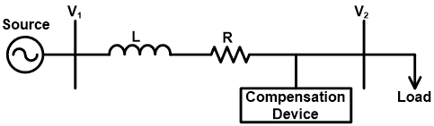
Series Compensation
In series compensation, the FACTS devices are connected in series with the power system network. This device can be a variable impedance like a capacitor or an inductor. Generally, the capacitor is connected in series with the transmission line. It is mostly used to improve the power transfer capability of EHV/UHV transmission lines.

The power transfer capacity of a transmission line without using compensation device;
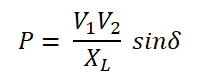
Where,
- V1 = Sending end voltage
- V2 = Receiving end voltage
- XL = Inductive reactance of transmission line
- δ = Phase angle between V1 and V2
- P = Power transferred per phase
Now, we connect a capacitor in series with the transmission line. The capacitive reactance of this capacitor is XC. So, the total reactance is XL-XC.
So, with a compensation device, the power transfer capacity is given by;
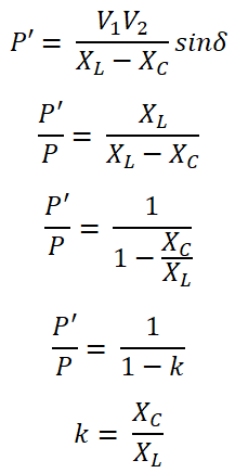
The factor k is known as the compensation factor or degree of compensation. Generally, the value of k is lies between 0.4 to 0.7. Let’s assume the value of k is 0.5.

Hence, it is clear that, if we use the series compensation devices, approximately 50% more power can be transfer.
By using the series capacitor, the angle between voltage and current (δ) is less compared to the uncompensated line. The lower value of δ will give better system stability. Hence, for the same amount of power transfer and the same value of sending end and receiving end, the compensated line will give better stability compared to the uncompensated line.
- Related Post: Busbars and Connectors in HV and EHV installations
Shunt Compensation
In a high voltage transmission line, the magnitude of receiving end voltage depends on the loading condition. The capacitance performs an important role in the high voltage transmission line.
When the line is loaded, the load needs reactive power. This reactive power demand fulfills by the line capacitance. When the load is more than SIL (surge impedance loading), then high demand for reactive power will result in a large voltage drop at receiving end of a transmission line. Therefore, the capacitor bank is connected in parallel with a transmission line at the receiving end to feed the demand for reactive power. So, it reduces receiving end voltage drop.
If the capacitance of the line increases, the receiving end voltage will increase.
When the line is lightly loaded (less than SIL), the reactive power demand is less compared to the line capacitance. In this condition, the magnitude of receiving end increases than the magnitude of sending end voltage. This effect is known as the Ferranti effect. To avoid this condition, the shunt reactor is used to connect in series with the transmission line at the receiving end. The shunt reactor will absorb extra reactive power from line and maintain receiving end voltage at rated value.

Types of FACTS Controllers
According to the type of connection FACTS Controller with the power system, it is classified as;
- Series Connected Controller
- Shunt Connected Controller
- Combined Series-Series Controller
- Combined Shunt-Series Controller

Series Connected Controller
The series controllers are used to introduced voltage in series with the line voltage. It consists of a capacitor or reactor (impedance devices). This type of controllers is used to supply or consume variable reactive power.
When the load of the transmission line is more, it needs extra reactive power. In this condition, it is used to supply reactive power with the help of a capacitor. When the transmission line operates on very light load, the receiving end voltage increase than the sending end voltage due to less demand for reactive power. In this condition, it is used to consumes reactive power with the help of an inductor.
In most of the case, the capacitors are installed at the end of the line to compensate demand for reactive power. For this purpose, Thyristor Controlled Series Capacitor (TCSC), and Static Synchronous Series Compensator (SSSC) are used. The below figure shows the basic diagram of series connected Controller.

Shunt Connected Controller
This type of device is used to inject current to the power system at the point of connection. Similar to the series-connected controllers, it also consists of variable impedance like capacitor and inductor.
When a capacitor is used to connect parallel with the power system, the method is known as shunt capacitive compensation. When the transmission line consists of a more inductive load, it operates on a lagging power factor. This method is used to draws current leading to the source voltage to compensate for the lagging load with the help of a shunt connected capacitor.
When an inductor is used to connect in shunt with the power system, the method is known as shunt inductive compensation. Generally, this method is not more useful with the transmission network. But in case of a very large transmission line, the load is disconnected or it operates on no-load or less load condition, due to the Ferranti effect, the receiving end voltage increase then the sending end voltage. to avoid this condition, the shunt inductive compensator is used.
- Related Post: SCADA Systems for Electrical Distribution
The example of this type of system is SVC (Static VAR compensator) and Static Synchronous Compensator).

Combined Series-Series Controller
In multilane transmission lines, a combination of separate series controllers is used in a coordinated manner to provide independent series reactive compensation for each line. But it can transfer real power with lines via power link. Or it can be connected with unified controllers that the DC terminals of converters are interlinked together. This will help to transfer the real power to the transmission line. An example of this type of system is the Interlink Power Flow Controller (IPFC).

Combined Shunt-Series Controller
This type of controller is used to introduce voltage in parallel using the shunt controller and along with it used to introduce the current is series using the series controller. But both controllers must operate with coordination. The example of this type of controller is the Unified Power Flow Controller (UPFC).

Types of FACTS Devices
Various FACTS devices are introduced to fulfill their application. Here we will discuss the most used FACTS devices or controller as listed below.
Series Compensator:
- Thyristor Controlled Series Capacitor (TCSC)
- Thyristor Controlled Series Reactor (TCSR)
- Thyristor Switched Series Capacitor (TSSC)
- Static Synchronous Series Compensator (SSSC)
Shunt Compensator:
- Static VAR Compensator (SVC)
- Thyristor Controlled Reactor (TCR)
- Thyristor Switched Capacitor (TSC)
- Thyristor Switched Reactor (TSR)
- Static Synchronous Compensator (STATCOM)
Series-series Compensator:
- Interline Power Flow Controller (IPFC)
Series-shunt Compensator:
- Unified Power Flow Controller (UPFC)
Let’s get understand in brief for each kind of compensator.
- Related Post: Overhead Lines Protection – Faults & Protection Devices
Thyristor Controlled Series Capacitor (TCSC)
In this method, the capacitive reactance connected in series with the power system. It consists of a capacitor bank in which multiple capacitors are connected in a series-parallel connection. The capacitor bank is connected in parallel with the thyristor-controlled reactor. It is used to provide a smooth variable series capacitance.
The thyristors are used to control the impedance of the system. The total impedance of the circuit can be controlled by controlling the firing angle of a thyristor. A simple block diagram is shown in the below figure.
Thyristor Controlled Series Reactor (TCSR)
This is a series compensator device that provides a smooth variable inductive reactance. This device is the same as TCSC, just the capacitor is replaced with the reactor. The reactor stops conducting when the firing angle is 180˚ and it starts conducting when the firing angle is below 180˚. The basic diagram of Thyristor Controlled Series Reactor (TCSR) is as shown in the below figure.
Thyristor Switched Series Capacitor (TSSC)
This Compensation technique is similar to the TCSR. In TCSR, the power controlled by controlling the firing angle of a thyristor. Hence, it provides stepwise control. But in the case of TSSC, the thyristor can only be on or off. There is no firing angle. So, the capacitor either fully connected or fully disconnected from the line. It will reduce the cost of the thyristor and reduce the cost of the controller. The basic diagram of TSSC is the same as the TCSC.
- Related Post: Integration of Renewable Energy with Grid System
Static Synchronous Series Compensator (SSSC)
It is a series compensation technique used in the transmission system. The power flow through the transmission line is regulated by controlling the equivalent impedance of the transmission line. The output voltage of SSSC is fully controlled and independent with the line current. Hence, by controlling the output voltage of SSSC, we can control the impedance of the line.
It is also considered as a static synchronous generator connected in series with the transmission line. This system aims to increase or decrease the voltage drop across the line. And hence it controls the power flow through the transmission line. This system injects voltage in quadrature with the line current. If supplied voltage leads current, it provides capacitive compensation and if supplied voltage lags current, it provides inductive compensation. The below figure shows the basic diagram of the Static Synchronous Series Compensator.
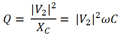
Static VAR Compensation (SVC)
In Static VAR Compensator, a fixed capacitor bank is connected in parallel with the thyristor-controlled inductor. The firing angle of the thyristor controls the reactor and hence it controls the voltage across the inductor. Therefore, the power drawn by the inductor can be controlled. The basic diagram of the Static VAR Compensator is as shown in the below figure.
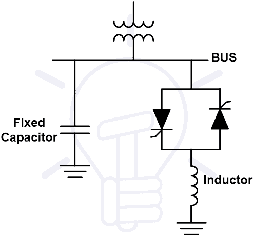
The SVC is used to improve power factor, regulating voltage, reduce harmonics, stabilize the transmission network. This type of device is also used in industries for reactive power control and improve power quality. The most commonly used SVCs are explained below.
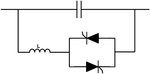
Thyristor Controlled Reactor (TCR)
In this type of controller, the reactor is connected in series with the thyristor valve. It consists of two thyristors connected in anti-parallel. These thyristors conduct an alternate half cycle of the power supply. The control circuit is used to give pulse to thyristor at every half cycle. The firing angle of the thyristor controls the amount of lagging power supply to the power system. Generally, this device is used in the EHV transmission line to provide reactive power during light load or no-load condition. The basic diagram of a Thyristor Controlled Reactor is as shown in the below figure.

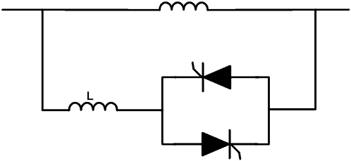
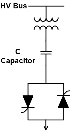
Thyristor Switched Capacitor (TSC)
During heavy load conditions, the reactive power demand increases. In this condition, the Thyristor Switched Capacitor (TSC) is used to fulfill the demand for reactive power. Generally, this type of device is used in the EHV transmission line and used in heavy load conditions. This device is the same as TCR just a reactor is replaced by a capacitor. Similar to TCR, the amount of power provide to the transmission line is controlled by controlling the firing angle of a thyristor. The basic diagram of the Thyristor Switched Capacitor (TSC) is as shown in the below figure.
Thyristor Switched Reactor (TSR)
This is similar to the Thyristor controlled reactor (TCR). In TCR, the firing angle of the thyristor is controlled to control the current from the device. But in case of the TSR, the thyristor either fully on or off. There is no phase control. So, because of the absence of firing control, the cost of the thyristor is less and it reduces the loss of switch. The basic diagram of the Thyristor Switched Reactor is the same as the Thyristor Controlled Reactor.
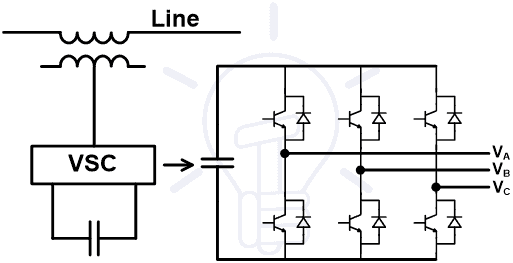
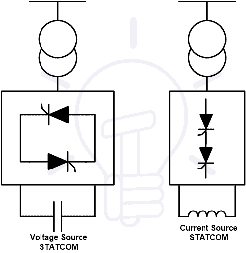
Static Synchronous Compensator (STATCOM)
STATCOM is a power-electronics based voltage source converter that can regulate electricity in the transmission system by source or sink of reactive power. It also used to provide active power to the transmission line. Generally, the STATCOM is used in the transmission line which has very poor power factor and poor voltage regulation. It is the most commonly used device to improve the voltage stability of the power system.
It uses the charged capacitor as the input DC source and converts it into three-phase AC voltage as output by the voltage-controlled inverter. The output of the inverter is synchronized with the AC power of the power system. The inverter is connected in a shunt connection with the transmission line via a coupling transformer. The output of STATCOM can be controlled by controlling the output of an inverter. The basic diagram of STATCOM is as shown in the below figure.
Interline Power Flow Compensator (IPFC)
In this type of compensation technique, the number of converters is connected with a common DC link and each converter is connected with a separate line. Therefore, this compensation technique is used in an only multiline transmission system. These converters are also capable to transfer the real power. So, in this method, the real and reactive both powers can equalize between the lines. The basic diagram of this technique is as shown in the below figure.

Unified Power Flow Controller (UPFC)
It is a combination of STATCOM and SSSC Coupled via a common DC voltage link. To produce current, it uses a pair of three-phase controllable bridges. And this current is injected into the transmission line using a transformer. It is used to improve the voltage stability, power angle stability, and damping of the system.
This device can control the real or active and reactive power flow in the transmission line. In abnormal conditions, the UPFC will not work. It only works under a balanced sine wave source. It is also used to suppress the oscillation power system and improve the transient stability of the power system. The basic diagram of the Unified Power Flow Controller (UPFC) is as shown in the below figure.

Advantages & Disadvantages of FACTS Devices
Advantages
The advantages of FACTS devices are listed below,
- The FACTS devices are used to increase the power transfer capability of the transmission line. Hence, it saves costs to develop an entirely new transmission line.
- It increases the loading capability of the transmission line of their thermal capability.
- It reduces the amount of reactive power in the transmission line. In this way, the transmission line can transfer more amount of active power to the load.
- The FACTS devices are used to control the amount of flow of power through the transmission line. So, it helps to follow the guideline and contract of utility and ensure the optimum flow of power.
- It reduces the cost of power as it reduces the transmission cost.
- It increases the quality of power, voltage stability, thermal stability, and transient stability of the system.
- FACTS devices are not containing any environmentally hazardous waste material. Hence, this technology of environmentally friendly.
- It improves the power factor of the power system network.
- It increases the reliability and flexibility of the transmission network.
Related Post: Power Transformers Maintenance, Diagnostic & Monitoring
Disadvantages
The disadvantages of FACTS devices are as listed below.
- The FACTS devices are used power electronics switches to control supply or absorb the power. The major disadvantage of the use of power electronics switch is that it induces harmonics in the output signals. These harmonics enter into the power system network. So, the active filters are used to remove the harmonics.
- The initial cost of FACTS devices is very high.
- It transmits a limited amount of power.
- It needs continuous maintenance and the repair cost of these devices are very high.
- It uses converters. Hence, the amount of power loss occurs in the switches.
- If the current from the FACTS devices is increased due to any reason, there may be a chance to damage the power electronics switches used in the converter. And the cost of these switches is very high.
Related Posts:
- Why Electric Power Transmission is Multiple of 11 i.e 11kV, 22kV, 66kV etc?
- What are the Colored Aerial Marker Balls on Power Lines For?
- Transformers Insulation Materials in Oil-Immersed & Dry Type T/F
- Failures In Electrical Systems, Equipments & Materials
- All About Electrical Protection Systems, Devices And Units
- Transformers Fire Protection System – Causes, Types & Requirements
- Short Circuit Currents And Symmetrical Components
- Power Distribution in Industries – All You Need to Know
- High Inrush Current in Capacitor Switching and Ways to Prevent It.
- Types of Electrical Wires and Cables
- Fault Current Limiter and Their Types
- What is HVDC? – High Voltage Direct Current Power Transmission
- Types of HVDC Systems and MTDC Configurations