Calculation & Design of Solar Photovoltaic Modules & Array
Determining the Number of Cells in a Module, Measuring Module Parameters and Calculating the Short-Circuit Current, Open Circuit Voltage & V-I Characteristics of Solar Module & Array
What is a Solar Photovoltaic Module?
The power required by our daily loads range in several watts or sometimes in kilo-Watts. A single solar cell cannot produce enough power to fulfill such a load demand, it can hardly produce power in a range from 0.1 to 3 watts depending on the cell area. In the case of grid-connected and industrial power plants, we require power in the range of Mega-watts or even Giga-watts.

Thus, a single PV cell is not capable of such high demand. So, to meet these high demands solar cells are arranged and electrically connected. Such a connection and arrangement of solar cells are called PV modules. These PV modules make it possible to supply larger demand than what a single cell could supply.
When solar radiation falls on a single solar cell potential is produced across it two terminals anode and the cathode (i.e. anode is the positive terminal and cathode is the negative terminal). To increase the potential for the required power N-number of cells are connected in series. The negative terminal of one cell is connected to the positive terminal of the other cell as shown in figure below.
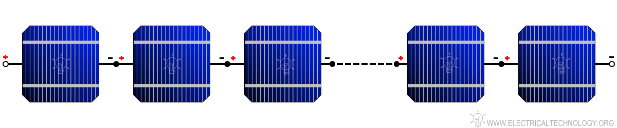
When we connect N-number of solar cells in series then we get two terminals and the voltage across these two terminals is the sum of the voltages of the cells connected in series. For example, if the of a single cell is 0.3 V and 10 such cells are connected in series than the total voltage across the string will be 0.3 V × 10 = 3 Volts.
- Related Post: How to Design and Install a Solar PV System?
If 40 cells of 0.6 V are connected in series than the total voltage would be 0.6 V × 40 = 24 Volts. It is important to note that when the cells are connected in series the voltage gets added while the current remains the same.
Similarly, when the cells are connected in parallel the current of the individual cells is added. The anode terminal of one cell is connected to the anode terminal of the next cell and similarly, the cathode terminal is connected to the cathode terminal of the next cell as shown in figure 2.
Unlike the series connection, the total voltage of the string in parallel connection remains unchanged. For example, if a cell has a current producing capacity of 2 A and 5 such solar cells are connected in parallel. Then the total current producing capacity of the cell will be 2 A × 5 = 10 A.

The PV module parameters are mentioned by the manufacturers under the Standard Test Condition (STC) i.e. temperature of 25 °C and radiation of 1000 W/m2. In most of the time and locations, the conditions specified under STC does not occur. This happens because the solar radiation is always less than 1000 W/m2 and the cell operating temperature is higher than 25 °C, this uncertainty results in reduced output power of the PV module.
As we discussed before that the PV module is made up of the number of solar cells, hence its parameters and factors affecting the generation of electricity are similar to that of the solar cell which we have already covered up in our previous article. So we won’t be covering that part here again.
Determining the Number of Cells in a Module
One of the basic requirements of the PV module is to provide sufficient voltage to charge the batteries of the different voltage levels under daily solar radiation. This implies that the module voltage should be higher to charge the batteries during the low solar radiation and high temperatures.
The PV modules are designed to provide the voltages in the multiple of 12 V battery level that is 12 V, 24 V, 36 V, 48 V, and so on. To charge a 12 V battery through a PV module we need a module having VM of 15 V and for 24 V battery we need a module with VM of 30 V and so on. Other devices used in the PV system are made compatible to be work with a battery voltage level.
To provide the required voltage level we need to connect cells in series. Depending on the different technologies used in the PV cell, the number of cells required to be connected in series will differ. The number of cells to be connected in series depends on the voltage at maximum power point i.e. VM of the individual cell and the voltage drop that occurs due to an increase in the temperature of the cell above STC.
Example:
Let us understand this with an example, a PV module is to be designed with solar cells to charge a battery of 12 V. The open-circuit voltage VOC of the cell is 0.89 V and the voltage at maximum power point VM is 0.79 V.
The cells operating temperature is 60 °C and there is a decrease in voltage by 2 mV for per degree Celsius rise in temperature. How many cells are required to be connected in series to charge the battery?
Step 1: Find the voltage at maximum power point VM = 0.79 V.
If VM is not specified then take VM as 80 to 85% of VOC.
Step 2: Find the loss of voltage under operating temperature i.e. at 60 °C.
Rise in temperature above STC = Operating temperature – Temperature at STC.
Rise in temperature above STC = 60 °C – 25 °C = 35 °C
Therefore, loss of voltage due to rise in temperature above STC:
Loss of Voltage = 35 °C × 0.002 V = 0.07 V
Step 3: Determining the voltage at the operating condition.
The voltage at the operating condition = Voltage at STC (VM) – loss of voltage due to a rise in temperature above STC.
Therefore, Voltage at the operating condition = 0.79 V – 0.07 V = 0.72 V
Step 4: Determine the required PV module voltage to charge the battery.
To charge a battery of 12 V we need module voltage to be around 15 V.
Step 5: Determine the number of cells to be connected in series.
The number of series-connected cells = PV module voltage / Voltage at the operating condition.
Number of series connected cells = 15 V / 0.72 V = 20.83 or about 21 cells
Thus, we need 21 series-connected cells to charge a 12V battery. It is important to note that for different solar cell technologies we will need a different number of cells in series for the same output voltage. An actual photo of the PV module which consists of N-number of electrically connected cells is shown in figure 3 below.
Related Posts:
- How to Wire Solar Panels in Series-Parallel Configuration?
- Series, Parallel and Series-Parallel Connection of Batteries
Measuring Module Parameters
For the measurement of module parameters like VOC, ISC, VM, and IM we need voltmeter and ammeter or multimeter, rheostat, and connecting wires.
Measurement of Open Circuit Voltage (VOC):
While measuring the VOC, no-load should be connected across the two terminals of the module. To find the open circuit voltage of a photovoltaic module via multimer, follow the simple following steps.
- Set the multimeter knob to DC voltage measurement and select the range for the voltage measurement accordingly i.e. 6 V, 12 V, 24 V, etc.
- Make sure that the one probe is connected to the COM port of multimeter and another to the voltage measuring port.
- After selecting the mode and range, connect the probes of the multimeter to the two terminals of the PV module and observe the reading on the display.
- Make sure that the positive probe (voltage measuring port) is connected to the positive terminal and negative probe (COM port) to the negative terminal. If the probes are connected vice versa it will give a negative reading.
- The reading on the display of the multimeter is the open-circuit voltage VOC of the PV module.
Related Post:
- Parameters of a Solar Cell and Characteristics of a PV Panel
- How to Design a Solar Photovoltaic Powered DC Water Pump?
Measurement of Short circuit current (ISC):
While measuring the ISC, no-load should be connected across the two terminals of the module.
To find the short circuit current of a photovoltaic module via multimer, follow the simple following steps.
- Set the multimeter knob to current measurement and select the range for the current measurement accordingly i.e. typically between 0.1 to 10 A.
- Make sure that one probe is connected to the COM port of multimeter and another to the current measuring port.
- After selecting the mode and range connect the probes of the multimeter to the two terminals of the PV module and observe the reading on the display.
- Make sure that the positive probe is connected to the positive terminal (current measuring port) and negative probe (COM port) to the negative terminal. If the probes are connected vice versa it will give a negative reading.
- The reading observed on the display of the multimeter is the short circuit current ISC of the PV module.
Related Posts:
- How to Wire Solar Panels & Batteries in Series-Parallel Connection?
- How to Wire Batteries in Series-Parallel to a Solar Panel?
Measuring the I-V Curve:
For measuring the I-V curve, the solar PV module must be connected in series with the variable resistor as shown in figure below.
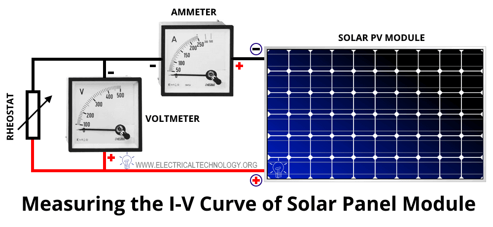
The negative terminal of the module is connected to the positive terminal of the ammeter and the voltmeter is directly connected across the PV module as shown in figure 4.
If unknowingly the connections are done vice versa then the reading obtained will have a negative sign, reconnect the meters to obtain correct values. Once done properly adjust the variable resistor (rheostat) on one side so that the voltage will be maximum and the current is minimum.
Note down the values of current and voltage at this position of the rheostat. Now slowly slide the rheostat to the other side and note down the readings for every slide adjustment until the rheostat is completely shorted. Calculate the power for every value of voltage and current by using the equation below.
P = V × I
Thus, by using these measured values all the other parameters of the PV module can be obtained.
Related Posts:
- How to Wire Solar Panels in Series & Batteries in Parallel?
- How to Wire Solar Panels in Parallel & Batteries in Series?
Modules with Higher Wattage
One of the most common cells available in the market is “Crystalline Silicon Cell” technology. These cells are available in an area of 12.5 × 12.5 cm2 and 15 ×15 cm2. It is difficult to find cell beyond this area in the market, most of the larger solar plant use modules with this cell areas.
But how much higher wattage thus this module can provide and how can obtain higher power per module? A typically designed PV module has a VM of 15 V to charge a battery of 12 V. To obtain this voltage 32 to 36 cells are connecting in series depending upon their operating temperature and peak voltage VM of an individual cell.
The current produced by cells depends upon the area, amount of light falling on it, angle of light falling on it, and current density. The Crystalline Silicon Cell has a current density JSC in a range of 30 mA/cm2 to 35 mA/cm2.
Let us take the current density of 30 mA/cm2 for our example. Then the short circuit current for an area of 12.5 × 12.5 cm2 can be calculated as;
ISC = JSC × Area = 30 mA/cm2 × 12.5 × 12.5 cm2 = 4.68 A
Similarly, for 15 ×15 cm2 the short circuit current is calculated as;
ISC = JSC × Area = 30 mA/cm2 × 15 × 15 cm2 = 6.75 A
For most manufacturers, the IM is about 90 to 95 % of ISC. For our example let is take IM as 95 % of ISC.
IM = 0.95 × ISC
Then the IM for an area of 12.5 × 12.5 cm2 can be calculated as;
IM = 0.95 × 4.68 A = 4.446 A
Similarly, for 15 ×15 cm2 IM is calculated as;
IM = 0.95 × 6.75 A = 6.412 A
Now we can determine the maximum peak power for these two cells;
PM = VM × IM
PM = 15 V × 4.446 A = 66.69 W (for an area of 12.5 × 12.5 cm2)
PM = 15 V × 6.412 A = 96.18 W (for an area of 15 × 15 cm2)
Therefore, by utilizing the best available cell technology having an area of 12.5 × 12.5 and 15 × 15 cm2 we get a power output of 66.69 W and 96.18 W respectively (Considering IM to be 95 % of ISC and current density of 30 mA/cm2).
To increase the voltage and current of the module more number of cells must be connected in series and parallel respectively, this will increase the overall power of the module more than what we have calculated.
Related Posts:
- How to Wire Solar Panels in Series & Batteries in Parallel?
- How to Wire Solar Panels in Parallel & Batteries in Series?
Example:
Now for better understanding let us design a PV module that can provide a voltage at maximum power VM of 45 V under STC and 33.5 V under 60 °C operating temperature. We will use the cells having an open-circuit voltage VOC of 0.64 V, having a 0.004 V decrease in VM per °C rise in temperature.
Step 1: Find the voltage at maximum power point VM.
If VM is not specified then take VM as 80 to 85% of VOC
Let us assume VM = 0.85 × VOC = 0.85 × 0.64 V = 0.544 V
Step 2: Find the loss of voltage under operating temperature i.e. at 60 oC.
Rise in temperature above STC = Operating temperature – Temperature at STC.
Rise in temperature above STC = 60 °C – 25 °C = 35 °C
Therefore, loss of voltage due to rise in temperature above STC = 35 °C × 0.004 V = 0.14 V
Step 3: Determining the voltage at the operating condition
The voltage at the operating condition = Voltage at STC (VM) – loss of voltage due to a rise in temperature above STC.
Therefore, Voltage at the operating condition = 0.544 V – 0.14 V = 0.404 V
Step 4: Determine the required PV module voltage
we need the module voltage to be around 33.5 V.
Step 5: Determine the number of cells to be connected in series
The number of series-connected cells = PV module voltage / Voltage at the operating condition.
Number of series connected cells = 33.5 V / 0.404 V = 82.92 or about 83 cells.
Now let us calculate how much power these 83 cells can produce under STC, having VM = 45 V, and let us take the same values of current for two cells from the previous example.
IM = 4.446 A (for an area of 12.5 × 12.5 cm2)
IM = 6.412 A (for an area of 15 × 15 cm2)
Now we can determine the maximum peak power for these two cells at a voltage of 45 V;
PM = VM × IM
PM = 45 V × 4.446 A = 200.07 W (for an area of 12.5 × 12.5 cm2)
PM = 45 V × 6.412 A = 288.54 W (for an area of 15 × 15 cm2)
Thus, according to the requirement of large power, such cells of larger areas are connected in series and parallel to form a PV module. Further, these PV modules can be connected in series and parallel to form a PV array that generates power in MWs.
Related Posts:
- How to Wire Solar Panels in Series-Parallel Configuration?
- Series, Parallel and Series-Parallel Connection of Batteries
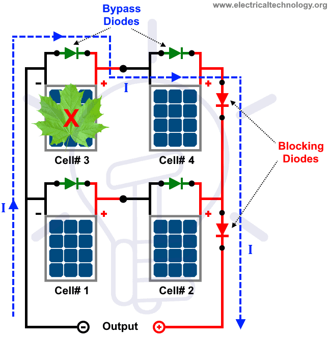
Blocking and Bypass Diodes
Bypass Diode
All the cells connected in series in the PV module are identical they all produce current when light falls on them. But if one of the solar cells gets shaded by some object the light falling on it is interrupted and it produces lower current or almost no current due to this interruption of light falling on the cell.
This cell will now act as a resistant to the current flow in the series string of the cells. It will act as a load and power generated by other cells will get dissipated in the shaded cell causing the cell’s temperature to rise and forming a hot spot. This may even lead to breaking of module glass, fires, and accidents in the system.
The bypass diodes are used to avoid such catastrophes in our designed system. As shown in figure 5 the bypass diode is connected in parallel to the solar cell with opposite polarity.
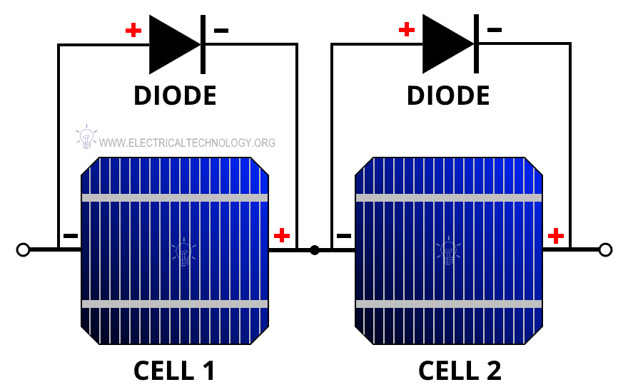
In normal no shading conditions, the bypass diode is reversed biased acting as an open circuit. But if shading occurs in the series-connected string of cells, the shaded cell will be reverse bias and this will act as a forward bias to the bypass diode as it is connected with an opposite polarity to the solar cell.
Now this shaded cell’s bypass diode will carry the current through this it rather than the shaded cell. Thus, the diode bypasses the cell avoids the damage caused by overheating hence the name bypass diode. Ideally, there should be one diode per solar cell in a module, but practically to make module cost-effective one bypass diode is connected for a series combination of 10-15 cells.
Related Posts:
- How to Wire Solar Panels & Batteries in Series-Parallel Connection?
- How to Wire Batteries in Series-Parallel to a Solar Panel?
Blocking Diode
In an off-grid system, the modules are used to supply the power to the load and charge the battery. During the night when there is no sunlight, the module produces no energy and the charge batteries start supplying power to the load and the PV module. The power supplies to the PV module is a loss of power. To avoid the loss a diode is placed to block the current flow from the battery to the PV module. Thus, it is due to this diode that the loss of power is avoided by blocking the current flow from the battery to the module.
Related Post:
Series, Parallel & Series-Parallel Connection of Solar Panels & Array
We have already explained very well this topic in our previous post labeled as Series, Parallel & Series-Parallel Connection of PV Panels. You will be able to wire to solar module strings and series array, parallel array or a combo of series and parallel string and arrays.
Related Posts:
- How to Wire Batteries in Parallel to a Solar Panel and UPS?
- How to Wire Batteries in Series to a Solar Panel and UPS?
- How to Wire Solar Panel to 12V DC Load and Battery?
- How to Wire Solar Panel to 120-230V AC Load and Inverter?
- How to Wire Solar Panel & Batteries in Parallel?
- How to Wire Solar Panel & Batteries in Series?
- How to Make a Simple Solar Cell? Working of Photovoltaic Cells
- Series, Parallel and Series-Parallel Connection of Batteries


I am designing a 3MW mini-substation for an existing thermosolar power facility in Tonopah, Nevada. I need some assistance in selection/bill of material for a 60kV disconnector and a 15kV fused disconnector. I will am the person doing both design and procurement
Dear Sir, Greetings! I would like to have your valuable feedback on our NEOM project. We have a fixed location on Tower mast and load is 550W, we need to know solar panel and batteries requirement for 50 hours backup time. Please note that there is no other power source, and it must be self-sustained with the solar system. I would really appreciate your support in this regard. Thank you in advance. sincerely.