Types of HVDC Systems and MTDC Configurations
Types of HVDC System Configurations & “MTDC” Multi Terminal DC Systems
The High voltage direct current or shortly known as HVDC is an efficient way to transmit power over long distances without experiencing too much power losses. But the HVDC system can connect in various configurations. Each of these configurations is used for their specific operations. This article briefly describes the types of HVDC system configurations.

There are mainly three types of HVDC system configurations
Back-to-Back HVDC Systems
In back-to-back or B2B configuration, both of the converter; rectifier & the inverter is installed inside the same terminal station & they are connected Back-to-Back with each other. It connects two AC power systems together i.e. it converts AC into DC using a rectifier & then immediately converts DC into AC using an Inverter.

It is installed inside a single room that interconnects two asynchronous AC power systems. Since they are connected back-to-back, there is no use of the DC transmission line. But the intermediate DC voltage is always kept low to reduce the number of thyristors being used in series & the current rating may go in the range of a couple of thousand amps.
It is used for connecting two asynchronous AC power systems that is;
- The two AC systems or power grids having different frequencies.
- The two systems having the same frequency but have a phase difference.
Two-Terminal HVDC System
In two-terminal HVDC configurations, there are two separate terminal stations i.e. converter stations where one of it is a rectifier & the other one is an inverter. The terminals are connected together by the HVDC transmission line to transmit power over a long distance.
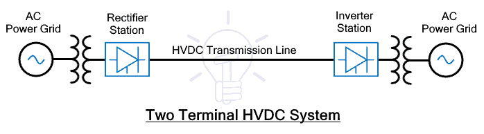
There are no parallel transmission lines or any intermediate tapping from its transmission line that is why it is also called point-to-point power transmission. It is used for supplying power between two points that are very far from each other.
The two-terminal HVDC system does not require an HVDC Circuit breaker because the AC circuit breaker on the AC side can be used to de-energize the DC line in case of maintenance & fault clearance. The AC circuit breakers are far simpler in design & cheaper in cost as compared to the DC circuit breakers.
- Related Post: Differences Between HVAC and HVDC – Power Transmission
Multi Terminal DC (MTDC) System
This type of HVDC configuration uses multiple transmission lines to connect more than two points. There are multiple terminal stations each with their own converter connected by the HVDC transmission line network. Some of these converters operate as rectifiers while others act as inverters. The power supplied by the rectifier’s combination is equal to the combined power received by the inverter (load) stations.

This type of DC network is equivalent to the AC grid that is flexible but it has the capability to control the power flow in the DC distributed network. Such type of network is much more complex than a two terminal HVDC configuration.
In MTDC System, we cannot use the AC circuit breaker on the AC side because it will de-energize the whole DC network instead of isolating the specific line having fault or scheduled maintenance. Therefore MTDC system requires multiple DC switchgear (circuit breaker) that can safely de energize the circuits or isolate it in case of maintenance work or fault clearance.
It is required to balance the system in such a way that the amount of current supplied by the rectifier stations is equal to the amount of current in the inverter station. In case of the high demand of power from any inverter station, the DC power is ramped up to meet the requirement. In doing so, it is necessary to monitor and control the voltage supplied as well as the inverters in case of overloading.
The MTDC systems are reliable in case of forced outage i.e. unexpected power failure from one of the many generation stations, the power supply is relocated through another converter station.
- Related Post: Advantages of HVDC over HVAC Power Transmission
Applications of MTDC:
- Connects multiple DC renewable energy farms to multiple power grids
- Connecting multiple offshore wind farms to the power grid
- Transfer of bulk power from multiple remote AC generating stations to multiple load centers.
- Allow interconnection between two asynchronous AC power systems
- Power supply reallocation in case of power failures in one of the generating stations.
- It can be used to offer more power to a heavily loaded AC network by using one rectifier & multiple inverters that injects power into the said AC network.
- Offers flexibility for power tapping at multiple points
The MTDC systems are classified into two main types;
Series MTDC System
In such configuration, multiple converter stations are connected in series with each other. Just like in a series circuit, the current flowing through each of the converter stations remains the same which is set by one station while the voltage drop may divide among the converter stations.
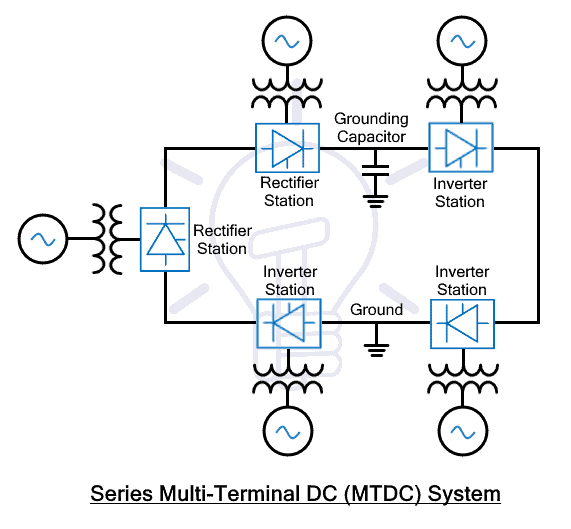
It is an extension of a two-terminal HVDC system with multiple converter stations in series as shown in the figure above. The converter stations are usually of lower capacity than the ones used in parallel MTDC systems.
This system usually uses monopolar DC links where the line is grounded at only one point. However, a grounding capacitor can be used at any other line for protection against transients.
The insulation coordination for the series MTDC system is quite complex due to the varying DC voltages at each station.
The power flow in parallel MTDC system is a little complex as compared to the parallel MTDC system because a parallel MTDC system can control its power flow by injecting current in a specific line while in series MTDC system, the power flow control is done by voltage control at each terminal station.
In a series MTDC system, the power flow reversal can be easily implemented using both VSC (Voltage Source Converter) & CSC (Current Source Converter).
In case of fault or scheduled maintenance in a specific line, the whole DC network will face a blackout. Therefore, just like a two-terminal system, the circuit breaker on the AC sides is used to de-energize the DC networks. The same is the case with the expansion of the series MTDC system. It is also quite difficult & requires the whole network to face blackout during the installation of new terminal stations. In order to install new terminal stations, the DC network (ring-shaped) must be split up at the point of installation which will break the supply to every other station in the path.
Parallel MTDC System
In the Parallel MTDC system, there are multiple converter stations (inverters) or load stations that are connected to a single converter station (rectifier) that supply power to the whole DC network. Just like a parallel circuit, the voltage remains constant or the same at all the inverter or load station that is set by one of the converter stations. While the current supply may change depending on the power demand. According to the power demand at each load station, the current is adjusted to balance the current supply. These terminal stations are generally of higher capacity than in series network.

The power reversal can be done with either voltage reversal or current reversal. In parallel MTDC system, the Voltage reversal (using CSC based terminal stations) affects all converter stations thus we need to implement a sophisticated control & communication system between these converters. However, if the power reversal is done using the current reversal technique (using VSC based terminal station) it will be much easier to realize. It is the reason, VSC (Voltage Source Converters) are preferred in parallel MTDC system instead of CSC.
Since the voltage remains constant in the VSC MTDC system, the current ratings of the valve converter decide the power rating of the terminal station.
It offers a wide range of power flow control in the DC network by injecting current in the specific line. This is more convenient than the power control in series systems using voltage control at each station.
The best feature of the Parallel MTDC system is that it if there is a fault in any terminal stations, the remaining DC network does not get affected. However, to isolate these specific DC lines, it does need a separate DC circuit breaker.
Also in case of expansion of the DC network, the power supply does not need to be interrupted because the new terminal is installed in parallel from these existing lines.
The insulation coordination in such a system is far more simple than in a series system because the voltage remains constant.
- Related Post: Overhead Lines Protection – Faults & Protection Devices
The parallel MTDC System is further divided into two categories;
Radial MTDC System
The radial MTDC system is a type of parallel MTDC configuration where a break in a transmission line or removal of one link will cause interruption of power supply to one or more than one converter station.

This figure shows 4 inverter stations connected with a single rectifier station. A break in one of the lines will surely interrupt the power supply to a minimum of one terminal station.
Because of such interruption in power supply, they are unreliable as compared to Mesh or Ring type MTDC system.
- Related Post: SCADA Systems for Electrical Distribution
Mesh (Ring) MTDC System
In Mesh or Ring MTDC system, the inverter (load) stations are connected with a single rectifier station in mesh or ring formation where a break in one transmission line or removal of one link does not interrupt the power supply to any inverter stations. The following figure shows a mesh or ring MTDC system.

As you can see, the removal of any link will not interrupt the power supply to any converter. In fact, the power will be routed through the other links. However, the other links must be designed to withstand the power transmission with power losses.
There is no power interruption in mesh type MTDC system. Therefore, parallel-connected mesh type MTDC system is more reliable than a parallel-connected radial type MTDC system.
Related Posts:
- Busbars and Connectors in HV and EHV installations
- What is Distributed Control System (DCS)?
- Design and Installation of EHV/EHV and EHV/HV Substations
- Power System Restoration – Outage, Voltage Collapse & Switching Programs
- Why Power Transmission Lines are Loose on Electric Poles Transmission Towers?