Automatic Phase Reverse Protection Using Contactors & Relay
Auto Phase Sequence Failure Panel using Contactors and Phase Sequence Protection Relay
Phase reverse protection is a critical aspect of electrical systems, particularly in three-phase power distribution networks and connected electrical machines. Incorrect phase sequence can lead to malfunctioning of machinery, equipment damage, and even safety hazards. To prevent such scenarios, a phase reverse protection panel can be implemented using contactors and phase sequence relays. In this article, we will show how to design and wire a phase reverse protection panel using contactors and 3-phase sequence protection relay with the help of power and control wiring diagrams.
Phase Reverse Protection
Three-phase power systems rely on the correct sequence of phases A, B, and C (i.e. L1, L2 and L3) for proper functioning. When the phases are in the correct order, electrical machinery and equipment operate as expected. However, if the phase sequence is reversed, the machinery might not operate correctly or even be damaged due to rotational direction changes.
For example, the motor will rotates in a reverse direction if a single phase (line) changed to the motor input terminals (e.g. if the Brown, Gray & Black is connected to the motor instead of Brown, Black, and Grey). You may find the practical case with wiring diagrams in the previous post of How to reverse-forward of 3-Phase motor using DOL starter?.
Phase reverse protection ensures that the phases are in the correct sequence before power is supplied to the machinery. This protection mechanism is crucial in preventing operational issues and damage.
Phase Sequence Relay
A phase sequence relay is an electrical device that monitors the order of incoming phases. It typically has three inputs (L1, L2, L3) for the three phases and outputs as (10-NO, 11-COM, 12-NC) with two indicators lights indicating the correct (Normal) or incorrect (Reverse) sequence. If the sequence is incorrect, the relay is used to trip the contactor and prevent power flow. You may use two contactors to prevent phase failure, with the second contactor providing power in the correct sequence, thereby ensuring smooth operation.
Components Required
To implement phase reverse protection, the following components are typically needed:
- 2 No of Contactors
- 3-Phase Sequence Protection Relay
- 4P-MCB and 3-P MCCB
- 2 NO of polit light indictors
- Single Phase & Three Phase Supply
- Wires & Cables
- Three-Phase Motor (optional as a load)
Wiring the Power and Control Circuit
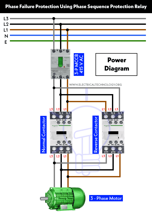
Power Diagram
Control Circuit Diagram
Click image to enlarge

Follow are the basic steps given below to wire an automatics phase sequence failure protection panel with labeling according to the given wiring, power and control circuit diagram.
- Connect the three-phase power supply of 415V AC from the 3-P MCCB to the L1, L2, and L3 terminals of the Contactor, and then the 3-Phase motor (U1, V1 & W1) respectively (Motor as load is optional e.g. any kind of 3-phase load can be connected through the power circuit).
- Connect the 3-Phases (Lines) from 4P-MCB to the three terminals (namely L1,L2,L3) of the phase sequence failure relay.
- Connect the 10-NO and 12-NC from the phase sequence relay to the 22-NC terminals of both (Normal and Reverse) contactor.
- For interlocking the contactors, connect the A1 and 21-NC terminals of normal contactor to the 21-NC and A1 terminal of reverse contactor respectively. This will prevent to operate both contacts at once i.e. only one contactor will be operational at a time either Normal or Reverse.
- Connect a direct phase line from the 4-MCCB to the 13-NO terminals of both contactors (Normal & Reverse).
- Now, Connect the Neutral wire from the 4-P MCB to the first terminals of indicators lights and A2 terminals of both contactors.
- Connect the second terminals of both indictor lights (Normal Mode and Phase Reverse) to the 14-NO terminals of both contactors.
- Finally, properly ground the motor, DOL starter, and control circuit to ensure safety.
Operation of the Phase Failure Protection Panel
When a phase reversal occurs among the three phases supplied by the power provider, the phase sequence protection relay detects the signal and triggers the circuit to automatically switch off the normal contactor while turning on the reverse contactor.
Upon the restoration of the proper phase sequence from the supply providers, the phase failure relay reverses the operation as described earlier. It switches off the reverse contactor and activates the normal contactor.
Both contactors are interlocked, ensuring that the circuit prevents the activation of both contactors simultaneously. For instance, only one contactor—either the Normal or Reverse one—will operate at a given time. This serves as an additional protective measure, preventing damage to the connected load as well as the protective devices themselves.
Related Posts:
- How to Control a 3-Phase Motor Using a Motor Protector?
- Automatic ON/OFF Circuit Using Two 8-PIN Timers for 1 & 3-Φ Load
- ON / OFF 3- Phase Motor Using 14-PIN Relay and DOL Starter
- How to Wire 14-PIN Relay for Holding or Latching Circuit?
- ON / OFF 3- Phase Motor Using 11-PIN Relay and DOL Starter
- How to Wire 11-PIN Relay for Interlocking and Holding Circuits?
- ON / OFF 3- Phase Motor Using 8-PIN Relay and DOL Starter
- How to Wire 8-PIN Relay for Holding or Latching Circuit?
- How to Control a Three-Phase Motor Using Solid-State Relay?
- Wiring of DOL Starter for Automatic / Manual Control Using Digital Timer
- How to Control a 3-Phase Motor Using a Foot Pedal Switch?
- Dahlander Motor: Speed Control using Dahlander Connection


