Difference Between Back Wiring, Side Wiring & Push-in Wiring
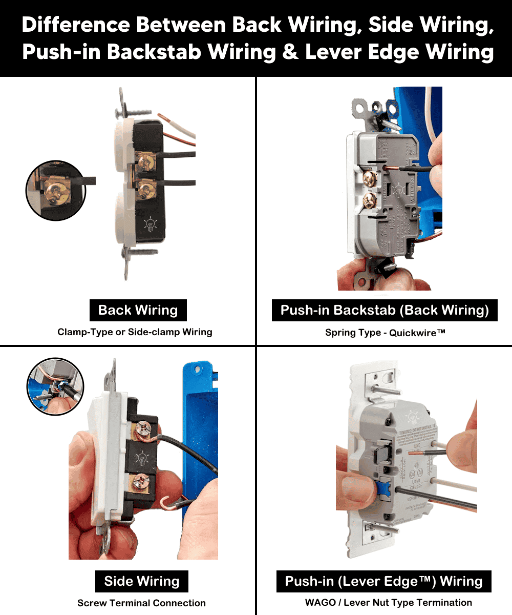
Difference Between Back Wiring, Side Wiring, Push-in Backstab Wiring & Lever Edge Wiring
When terminating devices such as switches, receptacles, outlets, dimmers, and similar wiring accessories, there are several acceptable wiring methods. Each termination method has specific advantages and limitations depending on the application, load requirements, installation environment, and long-term maintenance considerations.
In following wiring article, we will discuss and differentiate the most common device termination methods, such as:
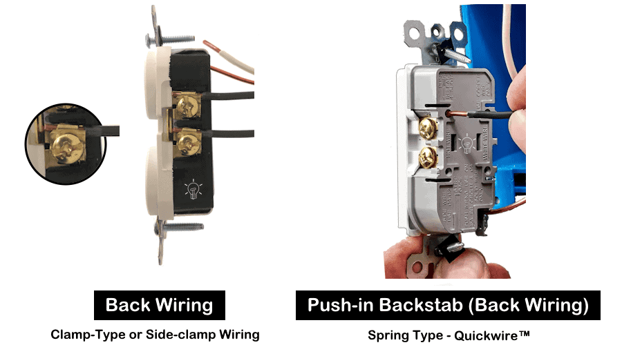
- Back wiring (clamp-type or side-clamp wiring)
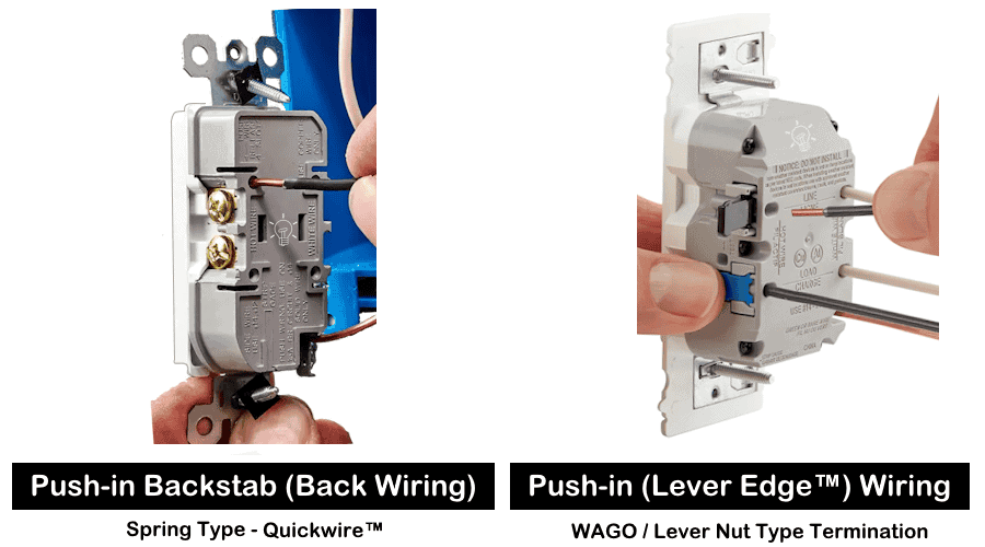
- Push-in backstab (spring-type termination, commonly used in QuickwireTM devices)
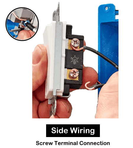
- Side wiring (screw terminal connection)
- Modern push-in lever wiring (e.g., Lever EdgeTM devices based on WAGO-style lever nut mechanisms)
What is a Back Wiring?
Back wiring (also known as clamp-type or side-clamp wiring) is a termination method where the conductor is inserted into a terminal located at the back of the device and secured by tightening a screw that clamps the wire internally.
In Back wiring method, electrical wires are connected to outlets or switches by inserting a straight, stripped wire into a hole on the back of the device and tightening a side screw to clamp it securely with a metal plate.
A metal plate moves up and down inside the device as you turn the terminal screw on the side, which clamping the wire securely.
There are two common methods used as back wiring:
- Screw-clamp Back Wire: It is a preferred professional method where a side screw tightens a pressure plate that clamps the wire.
- Backstab (Spring Type): Wire is pushed into a hole and held by an internal spring, such as QuickwireTM by Leviton. (don’t confuse with push-in wiring (lever-edge) as they are mechanically different).
To do back wiring termination, strip insulation to specified length and insert conductor straight into back terminal. Tighten terminal screw (for clamp type) OR push until spring engages (for backstab type).
This method is preferred by many electricians for reliability and speed and commonly used in residential and commercial applications for general receptacles and switches.
Advantages
- Cleaner installation (no wire loops around screws).
- Faster than traditional side wiring.
- Provides strong mechanical and electrical connection (clamp type).
- More secure than backstab when using screw-clamp design.
- Good for higher loads when clamp type is used.
What is a Side Wiring?
Side wiring is the traditional termination method where the stripped conductor is bent into a hook and wrapped clockwise around a terminal screw on the side of the device.
In side wiring, electrical wires are connected to devices like outlets or switches by looping a stripped wire clockwise around a side-mounted terminal screw and tightening it. It is a secure and preferred method with high-contact, and durable connection for safety and reliability over push-in (backstab) methods.
To do side wiring termination, strip insulation from the conductor as per requirement. Form a clockwise loop, shaped into a “J” or shepherd’s hook using pliers and rap around terminal screw. Tighten screw to the specified torque range to secure. Make sure the insulation does not get under the screw head.
Similar to back wiring, side wiring are used in standard residential installations, repairs and retrofits. They are especially used in situations requiring visible confirmation of connection quality.
Advantages
- Very reliable when properly installed.
- Strong mechanical bond.
- Widely accepted and code-compliant everywhere.
- Easy to inspect visually.
- Works with both solid and stranded wire.
What is a Push-in Wiring?
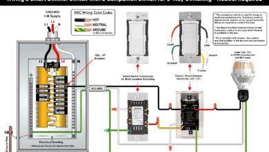
Push-in wiring (Lever EdgeTM by Leviton) is an innovative termination mechanism designed for faster, safer and easy installation of switches and outlets using color-coded lever terminals instead of screws.
The termination method for lever edge switches and receptacles are inspired by the modern connectors (like WAGO known as lever nut) which used spring action clamp for termination.
They feature a push-in, snap-down mechanism for copper wiring, providing an audible click for secure connections without exposed metal parts.
Lever Edge devices use a spring-action clamp mechanism that works with 14AWG (for 15A) or 12AWG (for 20A) solid and stranded copper wire.
These user-friendly receptacles and switches can be installed in seconds as they feature color-coded levers (hot, neutral, ground) which are easily identified.
They are UL & CSA approved and compatible with NEC. Hence, they can be confidently used for residential, commercial, and industrial applications.
Advantages
- Extremely fast installation, save time which reduces the labor cost.
- No screw required.
- Strong and secure wiring connections.
- UL / CSA listed and compliant with NEC.
- Reusable i.e. they can be removed and rewired again.
- Works with both solid and stranded wire for 15A and 20A circuits.
Resources:
- Wire Nut vs WAGO Connector: Which One is Better and Why?
- Stranded Wire vs. Solid Wire: Which is Better and Why?
- Difference Between 1-Pole and 2-Pole Breakers – NEC & IEC
- Difference Between Circuit Breaker and GFCI
- Difference Between BR and CH Breakers and Load Centers
- Difference Between Homeline and QO Breakers and Panels
- Wire Nuts and Connectors Color Codes – Wire and Gauge Sizes
- Electrical Wiring Color Codes for AC & DC – NEC & IEC
- Types of Electrical Wires and Cables
- Different Types of Wiring Systems and Methods of Electrical Wiring
- Can you use 15A Breaker on 20A Circuit and Vice Versa?
- Can I Use a 1-Phase Breaker on a 3-Phase Supply & Vice Versa?
- Can I Use a 240V Breaker on a 120V Circuit and Vice Versa?
- Can You use a 15A Outlet on a 20A Circuit and Vice Versa?
General Outlets and GFCI/AFCI Receptacles Wiring
- How to Wire an Outlet Receptacle? Socket Outlet Wiring Diagrams
- How to wire a GFCI Outlet?
- How to Wire GFCI Combo Switch and Outlet
- How to Wire an AFCI Combo Switch
- How to Wire an AFCI Outlet?
- How to a Wire 3-Way Combination Switch and Grounded Outlet?
- How to Wire Combo Switch and Outlet? – Switch/Outlet Combo Wiring Diagrams
- How to Wire a 15A – 120V Outlet – NEMA 5-15 Receptacle
- How to Wire a 20A – 120V Outlet – NEMA 5-20 Receptacle
- How to Wire a 15A – 240V Outlet – NEMA 6-15 Receptacle
- How to Wire a 20A – 240V Outlet – NEMA 6-20 Receptacle
- How to Wire a 50A – 125/250V Outlet – NEMA 14-50 Receptacle
Standard Breakers & GFCI Breakers Wiring Installations
- How to Wire a 1-Pole GFCI
- How to Wire a 2-Pole GFCI
- How to Wire a 3-Phase, 3-Pole GFCI
- How to Wire a 1-Pole Breaker
- How to Wire a 2-Pole Breaker
- How to Wire a 3-Pole Breaker
- How to Wire a Tandem Breaker
- How to Wire GFCI Circuit Breakers
- How to Wire an AFCI Breaker
Main Panels Wiring Tutorials
- How to Wire 120V/240V Main Panel? Breaker Box Installation
- How to Wire 208V/120V, 1-Phase & 3-Phase Main Panel?
- How to Wire 240V, 208V & 120V, 1 & 3-Phase, High Leg Delta Main Panel?
- How to Wire 277V/480V, 1-Phase & 3-Phase Main Service Panel?
- How to Wire a Subpanel? Main Lug Installation for 120V/240V
- How To Wire a Single Phase kWh Meter – 120V/240V
- How to Wire a Three-Phase Meter? 120/208/240/277/347/480/600V