Power Factor Correction Calculator – How to Find P.F Capacitor in µF & kVAR?
How to Calculate Capacitor in kVAR & µF for Power Factor Improvement? Calculator & Example
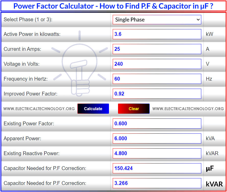
Power Factor Calculator
The following P.F calculator will calculate the existing or current power factor, apparent power “S” in kVA, existing reactive power “Q” in kVAR and the value of needed capacitor for P.F correction in microfarad “µF” and kVAR.
To calculate the value of capacitance of a capacitor bank in µF and kVAR, existing power factor, current reactive power in kVAR and apparent power in kVA, just enter the values of real or active power in kW, current in amps, voltage in volts, frequency in Hz (50 or 60Hz), select supply voltage system (single or three phase) and the targeted power factor (the value of needed or corrected power factor) and hit the “Calculate” button to the get the result of capacitance in μF, S in kVA and Q in kVAR.
- Related Calculator: Capacitor Bank in kVAR & µF Calculator for Power Factor Correction
Good to Know:
- Both kVAR and μ-farad are terms used in capacitor banks and power factor improvement & correction to eliminate the reactive components from the load side which has multiple advantages.
- This power factor calculator can be used for educational purposes which does not differentiate between lagging or leading power factor.
- We assume inductive load as power factor plays an important role in inductive circuits. Capacitive circuits provide leading power factor and the value of power factor is unity “1” in pure resistive circuits.
- The power factor correction capacitor must be connected in parallel with each phase load.
Related Posts:
- kVAR to Farad Calculator – How to Convert kVAR to μ-Farads?
- μ-Farad to kVAR Calculator – How to Convert Farads to kVAR?
Power Factor Calculation Formula
Single Phase P.F Calculation
The following formula can be used to calculate power factor in single phase AC circuits.
- Cosθ = P / S
- Cosθ = P / V x I
- Cosθ = kW / kVA
- Cosθ = True Power/ Apparent Power
- Cosθ = R/Z
Where:
- Cosθ = Power factor
- P = Real power in kW
- S = Apparent power in kVA
- V = Voltage in Volts
- I = Current in Amps
- R = Resistance in Ohms “Ω”.
- Z = Impedance (Resistance in AC circuits i.e. XL, XC and R known as Inductive reactance, capacitive reactance and resistance respectively) in Ohms “Ω”.
Three Phase P.F Calculation
Calculation with Line to Line Voltage (VL-L)
Cosθ = kW / √ (3 x VL-L x I)
Calculation with Line to Neutral Voltage (VL-N)
Cosθ = kW / 3 x VL-N x I
Related Posts:
- How to Convert Capacitor Farads into kVAR & Vice Versa for P.F
- How to Calculate the Suitable Capacitor Size in Farads & kVAR for P.F
Capacitor in Microfarad & kVAR Calculation for P.F
The following formulas can be used to calculate the capacitance of a capacitor in farad and microfarad for power factor correction.
- C = 159.155 x 10⁶ x Q in kVAR ÷ f x V2 … in microfarad
- C = 159.155 x Q in kVAR ÷ f x V2 … in Farad
or
- C = kVAR x 109 ÷ (2π x f x V2) … in microfarad
- C = kVAR x 103 ÷ (2π x f x V2) … in Farad
Additionally, the required capacitor bank in kVAR can be calculated as follow:
- Required Capacitor kVAR = P in kilowatts (Tan θ1 – Tan θ2)
- kVAR = C x f x V2 ÷ (159.155 x 10⁶) … in kVAR
- kVAR = C x 2π x f x V2 x 10-9 … in kVAR
Where:
- C = Capacitor in microfarad
- kVAR = Reactive Power
- f = Frequency in Hertz
- V = Voltage in volts
Good to Know:
The following formulas for Impedance “Z”, active power “P”, reactive power “Q” and apparent power “S” are useful while calculating the value of desired power factor and capacitor bank in kVAR and µF.
Impedance “Z” :
- Z = √ (R2 + (XL + XC)2) … Z, R, XL, XC in Ohms
- XL = 2πfL … L is inductance in Henry
- XC = 1/ 2πfC … C is capacitance in Farads
Active Power “P” :
Real or True Power or Active Power = √ (Apparent Power2 – Reactive Power2) or
- P = V x I x Cosθ … (in Single phase AC Circuits)
- P = √ (S2 – Q2)
- P =√ (VA2 – VAR2)
- P = √ 3 x VL-L x I x Cosθ … (in Three Phase Line to Line)
- P = 3 x VL-N x I x Cosθ … (in Three Phase Line to Neutral)
- kW = √ (kVA2 – kVAR2)
Reactive Power “Q” :
Reactive Power = √ (Apparent Power2 – True power2)
- Q = V I Sinθ
- VAR = √ (VA2 – P2)
- kVAR = √ (kVA2 – kW2)
Apparent Power “S” :
Apparent Power = √ (True power2 + Reactive Power2)
- S = V I
- S = √ (P + Q2)
- kVA = √ (kW2 + kVAR2)
Related Posts:
How to Calculate Power Factor & Capacitor in µF & kVAR
The following example shows how to calculate the required power factor, correction capacitor rating for capacitor bank in microfarad and kVAR, existing reactive power, active power and apparent power. You may compare the result of the solved example with the power factor calculator results.
Example:
A Single phase 240V, 60Hz, motor takes a supply current of 25A at a P.F (Power factor) of 0.60. The motor power factor has to be improved to 0.92 by connecting a capacitor in parallel with it. Calculate the required capacity of Capacitor both in microfarads and kVAR.
Solution:
Step 1: Calculate the Active Power of Load:
P = V x I x Cosθ1
- P = 240V x 25A x 0.6
- P = 3.6 kW
Additionally,
Actual KVA at Current lagging P.f
P = V x I
- P = 240V x 25A
- P = 6 kVA
Actual kVAR at Current lagging P.f
kVAR = √ (kVA2 – kW2)
- kVAR = √ (62 kVA – 3.62 kW)
- kVAR = 4.8 kVAR
Actual kVAR at Current lagging P.f
Step 2: Calculate the required kVAR for power factor correction
Existing P.F = Cosθ1 = 0.60
Needed P.F = Cosθ2 = 0.92
θ1 = Cos-1 = (0.60) = 53°.130; Tan θ1 = Tan (53°.130) = 1.333
θ2 = Cos-1 = (0.92) = 23°.073; Tan θ2 = Tan (23°.073) = 0.426
Required Capacitor kVAR to improve power factor from 0.60 to 0.92
Required Capacitor in kVAR
Required Capacitor kVAR = P in kW (Tan θ1 – Tan θ2)
kVAR = 3.6kW x (1.333 – 0.426)
VAR = 3265.2 VAR
Required kVAR = 3.2652 kVAR
Step 3: Convert kVAR to Microfarad
Required Capacitor in µF
C = kVAR x 109 ÷ (2π x f x V2) … in microfarad
C = 3.2625 kVAR x 109 ÷ (2π x 60Hz x 2402 V)
C = 150.4 µF
Related Electrical and Electronic Engineering Calculators:
- Circuit Breaker Size in Amps Calculator
- Electrical Wire & Cable Size Calculator (Copper & Aluminum)
- Wire & Cable Size Calculator in AWG
- Advance Voltage Drop Calculator and Voltage Drop Formula
- 3, 4, 5 and 6 Band Resistor Color Code Calculators
- kVA to Amps Calculator – How to Convert kVA to Amps?
- Amps to kVA Calculator – How to Convert Amps to kVA?
- Amps to Watts Calculator & Conversion – DC/AC (1 & 3 Phase)
- Watts to Amps Calculator & Conversion – DC/AC (1 & 3 Phase)
- Electricity Bill Calculator – How to Calculate your Electric Bill – Examples
- Energy and Power Consumption Calculator – kWh Calculator
- Electric Energy Cost Calculator – Cost of Energy Calculation


