Thevenin’s Theorem in DC Circuit Analysis
In 1893, a French engineer, M. L. Thévenin, made one of these quantum leaps to analyze electric circuits. Thevenin’s Theorem (also known as the Helmholtz-Thévenin Theorem) is not, by itself, a circuit analysis tool, but rather the foundation for a highly useful method of simplifying active circuits and complex networks. This theorem is particularly valuable for quickly and efficiently solving complex linear circuits and electrical and electronic networks.
Thevenin’s Theorem may be stated below:
Any linear electric network or a complex circuit with current and voltage sources can be replaced by an equivalent circuit containing a single independent voltage source VTH and a Series Resistance RTH.
- VTH = Thevenin’s Voltage
- RTH = Thevenin’s Resistance
Related Post: Norton’s Theorem. Easy Step by Step Procedure with Example (Pictorial Views)
Steps to Analyze an Electric Circuit using Thevenin’s Theorem
- Open the load resistor.
- Calculate / measure the open circuit voltage. This is the Thevenin Voltage (VTH).
- Open all current sources and short all voltage sources.
- Calculate /measure the open-circuit resistance. This is the Thevenin Resistance (RTH).
- Redraw the circuit using measured open circuit voltage (VTH) in Step (2) as the voltage source and the measured open circuit resistance (RTH) from step (4) as the series resistance. Connect the load resistor removed in Step 1. This forms the equivalent Thevenin circuit of original linear network or complex circuit.
- Find the Total current flowing through the load resistor by using the Ohm’s Law: IT = VTH / (RTH + RL).
By following these simple steps, complex networks and circuits can be effectively analyzed and simplified using Thevenin’s Theorem.
Related Post: SUPERMESH Circuit Analysis | Step by Step with Solved Example
Solved Example using Thevenin’s Theorem:
Example:
Find VTH, RTH, the load current IL flowing through the load resistor, and the load voltage across it in Fig. 1 using Thevenin’s Theorem.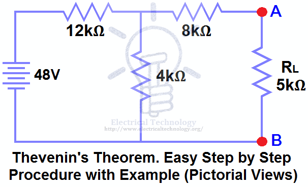
Solution:-
STEP 1.
Open the 5kΩ load resistor (Fig 2).
STEP 2.
Calculate / measure the open circuit voltage. This is the Thevenin Voltage (VTH) as shown in Fig (3).
We have already removed the load resistor from Fig. 1, so the circuit becomes an open circuit, as shown in Fig. 2. Now we need to calculate the Thevenin voltage.
Since a current of 3mA of current flows through both the 12kΩ and 4kΩ resistors (they are in series), no current flows through the 8kΩ resistor because it is an open circuit.
The voltage drop across the 4kΩ resistor based on V = I × R is:
3mA × 4kΩ = 12V
We also know that the 8kΩ resistor is in parallel with the 4kΩ resistor. In parallel branches, the voltage is the same, so the 8kΩ resistor will also have 12V across it. Therefore, 12V appears across terminals A and B, i.e.:
VTH = 12V

STEP 3.
Open all current sources and short all voltage sources, as shown in Fig. 4.

STEP 4.
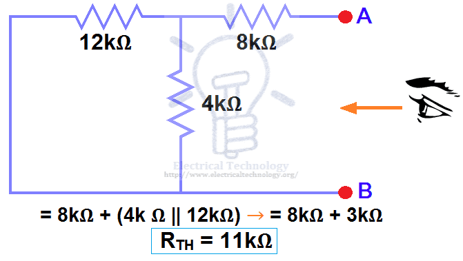
Calculate / measure the open circuit resistance. This is the Thevenin Resistance (RTH).
We have removed the 48V DC source to zero by replacing it with a short circuit in Step 3 (as shown in Fig. 3). We can see that the 8kΩ resistor is in series with the parallel combination of the 4kΩ resistor and the 12kΩ resistor, i.e.:
8kΩ + (4k Ω || 12kΩ) ….. (|| = in parallel with)
RTH = 8kΩ + [(4kΩ × 12kΩ) / (4kΩ + 12kΩ)]
RTH = 8kΩ + 3kΩ
RTH = 11kΩ
STEP 5.
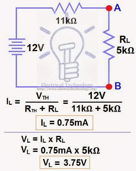
Connect the RTH in series with voltage source VTH and re-connect the load resistor. This is shown in fig (6) i.e. Thevenin circuit with load resistor. This is the Thevenin’s equivalent circuit.

STEP 6.
Now, apply the last step i.e. Ohm’s law . Calculate the total load current and load voltage as shown in fig 6.
IL = VTH / (RTH + RL)
IL = 12V / (11kΩ + 5kΩ) → = 12/16kΩ
IL = 0.75mA
And
VL = IL × RL
VL = 0.75mA × 5kΩ
VL= 3.75V
Now compare this simple circuit with the original circuit shown in Figure 1. Do you see how much easier it becomes to measure and calculate the load current in a complex circuit or network for different load resistors using Thevenin’s Theorem? Yes! and only yes.
Good to know: Both Thevenin’s and Norton’s theorems can be applied to both AC and DC circuits containing various components such as resistors, inductors, and capacitors. Keep in mind that the Thevenin voltage (VTH) in an AC circuit is expressed in complex form (polar notation), whereas the Thevenin resistance (RTH) is given in rectangular form.
- Related Posts:
- Maximum Power Transfer Theorem for AC & DC Circuits
- Kirchhoff’s Current & Voltage Law (KCL & KVL) | Solved Example
- Compensation Theorem – Proof, Explanation and Solved Examples
- Substitution Theorem – Step by Step Guide with Solved Example
- Millman’s Theorem – Analyzing AC & DC Circuits – Examples
- Superposition Theorem – Circuit Analysis with Solved Example
- Tellegen’s Theorem – Solved Examples & MATLAB Simulation
- SUPERNODE Circuit Analysis | Step by Step with Solved Example
- SUPERMESH Circuit Analysis | Step by Step with Solved Example
- Voltage Divider Rule (VDR) – Solved Examples for R, L and C Circuits
- Current Divider Rule (CDR) – Solved Examples for AC and DC Circuits
- Star to Delta & Delta to Star Conversion. Y-Δ Transformation
-
 How to Install a Wireless Smart Scene Switch
-
 How to Wire Smart Scene Controller Switch
-
 How to Install a Home and Away Wireless Smart Switch
-
 How to Install a Wire-Free Smart Dimmer Anywhere Companion
-
 How to Wire a Smart Wireless Switch and Anywhere Companion
-
 Wiring a Smart Dimmer Switch Companion with a Digital Dimmer