Millman’s Theorem – Analyzing AC & DC Circuits – Examples
Millman’s Theorem for AC & DC Circuits – Step by Step Solved Examples
Millman’s Theorem
The Millman’s theorem is used in the circuit analysis when it has only branches in parallel. Therefore, this theorem is useful to calculate the voltage at the end of a circuit. The Millman’s theorem is only applicable to the circuit which contains a parallel network.
Millman’s theorem is a combination of Thevenin’s theorem and Norton’s theorem. Sometimes, this theorem is also called as Parallel Generator Theorem. This theorem is proposed by electrical engineering professor Jacob Millman. And after his name, this theorem is named Millman’s theorem.
Millman’s theorem states that;
“The circuit having a number of voltage sources are connected in parallel with internal resistance can be replaced by a single equivalent voltage source in series with an equivalent resistance”
It means, we can find the voltage across the parallel branches of the given network. This theorem reduces the complexity of the network when a number of sources are connected as shown in the below figure.

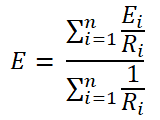
According to Millman’s theorem; the voltage across the load is;

Mathematical Equation
As shown in the above figure, the circuit having an n-number of voltage sources (E1, E2, E3, …, En). And the internal resistance of the sources is R1, R2, R3, …, Rn respectively. According to Millman’s theorem, any circuit can be replaced by the below network. The following fig shows the Millman’s equivalent circuit.

Now, we need to find the value of voltage source (E) and the equivalent resistance (R). The above circuit is similar to Thevenin’s equivalent circuit. Therefore, we can say that the voltage source (E) is the same as the Thevenin’s equivalent voltage (VTH) and the equivalent resistance is Thevenin’s equivalent resistance (RTH).
We find Norton’s equivalent circuit to make an easy calculation. For that, we will make a source transformation. And convert all voltage sources into the current sources.
We have an internal resistance connected in series with the voltage source. After source transformation, the voltage source is converted into the current source and the internal resistance is connected in parallel with the current source. Hence, the above circuit is converted as shown in the below figure.

According to ohm’s law, the value of the current sources will the E1/R1, E2/R2, E3/R3, …, En/Rn. Now, to find Norton’s equivalent current (IN), we need to short the load terminals. And find the current passes through that branch.

At node A1, the current divides into two paths. One path is through the resistance R1 and the second path is from the short-circuited branch. As we know, the current always flows through the low resistance path. Therefore, in this condition, the entire current passes through the short-circuited branch. And the current passes through the resistance is zero.
This same thing happens for all sources at node A2, A3, …, An. And current passes through all resistors is zero.
Now, at node A2, the current coming from node A1 is added. Similarly, at node A3, the current coming from node A2 is added. Therefore, at node An, current from all nodes added. The total current is a summation of all current and it is known as Norton’s current (IN).

So, we found Norton’s equivalent current. Now, we need to find Norton’s equivalent resistance. And for that, we need to remove all energy sources present in the circuit by open circuiting the current source and short-circuiting the voltage source.
In the above figure, we have only a current source. We will remove these current sources by open circuiting. And we need to remove the load to calculate the equivalent resistance. Therefore, the remaining circuit looks like the below figure.

As shown in the above figure, we can see that all resisters are connected in parallel. And this parallel combination is equal to the equivalent resistance.
Req = RN = R1 || R2 || R3 … || Rn

Now, put these values in Norton’s equivalent circuit as shown in the below figure.

If we convert this Norton’s equivalent circuit into Thevenin’s equivalent circuit, we can calculate the value of E and R from Norton current IN and Norton Resistance RN.
According to Ohm’s law;
E = IN x RN

Let’s make the above equation in general form for n-number of branches.

So, we have the value of the voltage source. And the value of equivalent resistance is equal to Norton’s equivalent resistance. Hence, we can get the Millman’s equivalent circuit (fig-2).
- Related Post: Norton’s Theorem. Step by Step Guide with Solved Example
Steps to Follow for Millman Theorem
Step-1 The Milliman’s theorem is the only applicable to the network or circuit having a greater number of parallel branches. So, we assume that we need to solve the circuit with has a number of parallel branches containing a voltage source connected in series with the internal resistance.
Step-2 Make a list of the internal resistance or resistance connected in series and the voltage sources.
Step-3 Find the equivalent resistance (R) across the load terminals with short-circuiting the voltage sources.
Step-4 Apply Millman’s theorem and find the value of voltage (E) across the load terminals. For that use equation-1. This voltage is the voltage across the load.
Step-5 Put the value of R and E in the Millman’s equivalent circuit (fig-2).
Step-6 Apply KVL to the loop to find the current passes through the load.
Analyzing DC Circuit Using Millman’s Theorem
Example #1
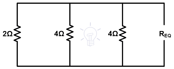
Find the current and voltage across the load terminal using Millman’s theorem.

Step-1 By observing the above figure, we can say that all four branches are connected in parallel. And we can apply Millman’s theorem.
Step-2 There are three branches except for the load branch. So, there are three voltages and three resistance as listed below.
E1 = 12V and R1 = 2Ω
E2 = 0V and R1 = 4Ω
E3 = 16V and R1 = 4Ω
Step-3 To find the equivalent resistance, we need to remove the voltage sources by short-circuiting and open the load terminals. Therefore, the remaining figure is shown in the below figure.

Req = 1Ω
As shown in the above figure, all resistances are in parallel. So, the equivalent resistance is;
Step-4 Now, apply Millman’s theorem.
In this example, we have 3 branches. Therefore, we use n=3.

Put the above listed values in this equation.
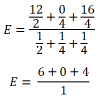
E = 10V
This is the voltage across the load terminal.
Step-5 Put these values in the Millman’s equivalent circuit.
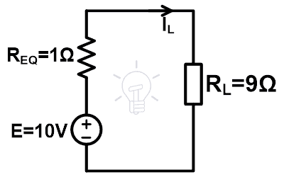
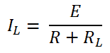
Step-6 According to ohm’s law,

IL = 1A
Hence, the voltage across the load is 10 V and the current that passes through the load is 1 A.
- Related Post: Tellegen’s Theorem – Solved Examples & MATLAB Simulation
Analyzing AC Circuit Using Millman’s Theorem
Example #2
Find the current and voltage across the load terminals using Millman’s theorem.
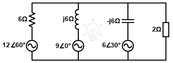
Step-1 As shown in the above figure four branches are connected in parallel. Therefore, we can apply Millman’s theorem.
Step-2 If we do not consider the load branch, there are three branches. To make the calculation easy, we will list the voltages and impedance. In the case of an AC circuit, we need to use word impedance instead of resistance.
The values of voltage sources are given in the polar form. But, the values of impedances are given in the rectangular form. So, we need to convert the values of the voltage source in polar form.
V1 = 12∠60° = 6 + j10.392
V2 = 9∠0° = 9 + j0
V3 = 6∠30° = 5.196 + j3
Impedances are given in rectangular forms. So, we list it as it is.
Z1 = 6Ω
Z2 = j6Ω
Z3 = –j6Ω
Step-3 Find the equivalent impedance. As shown in the above example, we need to remove all voltage sources by short-circuiting. And the remaining circuit is as shown in the below figure.
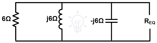
Here, all impedances are connected in parallel. So, the equivalent impedance will be;

Zeq = 6Ω
Step-4 Now, apply Milliman’s theorem,
Here, we have three branches. Therefore, n is equal to 3.

V = 6 + 1j0.392 – j9 + j5.196 – 3
V = 3 + j6.588
Now, we need to find the RMS value.
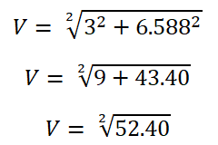
V = 7.23V
Step-5 Put these values in the Millman’s equivalent circuit.
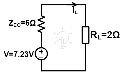
Step-6 According to ohm’s law,

IL = 0.9A
- Related Post: Maximum Power Transfer Theorem for AC & DC Circuits
Limitation of Millman’s theorem
Millman’s theorem is very helpful to solve the network. But there is some limitation which is listed as below.
- This theorem does not apply to the circuit having a dependent source between the independent source.
- For the circuit having less than two independent sources, this theorem is not useful.
- This theorem does not apply to the circuit having only series elements.
- When there is an element connected between the source, this theorem cannot be applicable.
Applications of Millman’s Theorem
The Millman’s theorem is widely used in the network analysis to solve the complex circuits. The Application of Millman’s theorem is as listed below.
- Millman’s theorem is most useful to find the voltage and current of load impedance in case of a greater number of parallel branches are available with a number of voltage sources.
- The calculation of this theorem is easy. It does not require to use of more equations.
- This theorem is used to solve the complex circuit having complex elements like Op-Amp.
Related Electric Circuit Analysis Tutorials:
- SUPERNODE Circuit Analysis – Step by Step with Solved Example
- SUPERMESH Circuit Analysis – Step by Step with Solved Example
- Kirchhoff’s Current & Voltage Law (KCL & KVL) | Solved Example
- Cramer’s Rule Calculator – 2 and 3 Equations System for Electric Circuits
- Wheatstone Bridge – Circuit, Working, Derivation and Applications
- Electrical and Electronics Engineering Calculators
- 5000+ Electrical and Electronic Engineering Formulas & Equations


