Substitution Theorem – Step by Step Guide with Solved Example
Analyzing & Solving Electric Circuits Using Substitution Theorem
Substitution Theorem
As the name suggests, a substitution theorem is used to replace one element of the circuit with another element. But while replacing the element, you must keep in mind that the behavior of the circuit should not change.
Substitution theorem states that;
“If we know the voltage across any branch and the current passing through that branch, we can replace that branch with various elements provided that the voltage and current should not change through that branch.”
This theorem is used to prove several theorems. To replace a branch of the network, this theorem tells us the boundary conditions.
If the value of current passes through the branch and the value of voltage across the branch is known, we can replace this branch with other elements like a voltage source, current source, different values of resisters, etc. by doing this, the initial condition remains unaltered.
This theorem cannot applicable when a circuit having more than two sources that are connected either in series or parallel.
Explanation of Substitution Theorem
The substitution theorem is a replacement of any branch of a network with an equivalent branch having different elements. In this theorem, if any branch or element is replaced by a voltage and current source which is the same as the original network has the voltage and current of that branch.
Let’s understand the substitution theorem with a network shown in the below figure.
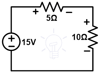
As shown in the above figure, it has two resistors connected in series with a DC source. Now, we will try to replace any branch or element with other elements. Before that, we need to know the voltage and current that pass through all branches.
Here, this circuit has only one loop. Therefore, the current passes through all the branches and elements is the same. This current can be determined by applying KVL to the network.
Let say, I amount of current that passes through the loop.
+15 = 5I + 10I
15 = 15I
I = 1A
So, the current that passes through each element is 1A. Now, we need to find the voltage across all elements.
One branch has a voltage source. So, we do not find the voltage of that branch. This voltage divides into two resistors. And we need to find the voltage across each resistor. It can be found by applying the voltage divider rule.
So, the voltage across 5Ω resistor is;
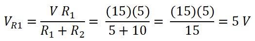
Similarly, the voltage across 10Ω resistor is;

- Related Post: Norton’s Theorem. Step by Step Guide with Solved Example
Substitute-1
We can replace the 10Ω resistor branch with a 10V voltage source as shown in the below figure.
Now, apply KVL to the network,
+15 – 10 = 5I
5 = 5I
I = 1A
So, the loop current is the same as the original circuit. Now, calculate the voltage across elements. The 10Ω resistor branch is replaced with a 10V source. Therefore, the voltage across that branch is 10V. And this voltage is the same as the voltage of that branch in the original circuit.
Now, find the voltage across the 5Ω resistor branch. The current passes through this branch is 1A. Therefore, according to Ohm’s law;
V5Ω = 1A × 5 = 5V
So, the current passes through all branch and the voltage across all branches are same as the original network.
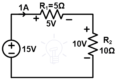
Substitute-2
Remove 5Ω resistor branch. And replace this branch with a 5V voltage source. The circuit diagram of this substitution is as shown in the below figure.

Now, calculate the current and voltage of all branches and compare it with the original network.
To find the current passing through the loop, apply KVL;
+15 – 5 = 10I
10 = 10I
I = 1A
Therefore, the loop current or the current that passes through the elements is the same as the current that passes through the original network.
The 5Ω resistor branch is replaced with a 5V voltage source. Hence, the voltage of this branch is the same as the voltage in the original network. Now, we need to calculate the voltage across the 10Ω resistor branch.
The current passes through the 10Ω resistor branch is 1A. According to Ohm’s law;
V10Ω = IR
V10Ω = 1 × 10
V10Ω = +10 V
So, after replacing the 5Ω resistor with a 5V voltage source, the behavior of the network is not changed.
Substitute-3
Remove the 10Ω resistor branch and replace it with a current source of 1A. The circuit diagram after substitution is as shown in the below figure.
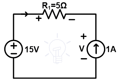
There is a current source in the circuit. Therefore, the current passes through the loop are the same as the amount of the current source. In this condition, 1A current source is connected to the network. And hence, the current that passes through the loop is 1A which is the same as the current passes through the original network.
Now, calculate the voltage across the 5Ω resistor and 1A current source.
According to Ohm’s law,
V5Ω = IR
V5Ω = 1 × 5
V5Ω = +5 V
Now, find the voltage across 1A current source. Let’s assume the voltage across 1A current source is V.
From the above figure;
+15 – 5 – V = 0
V = +10 V
So, it’s proven that the voltage across and current passes through all elements is the same as the original network after substituting the 10Ω resister with 1A current source.
Substitution-4
Remove the 10Ω resister branch and substitute it with a 5Ω resistor connected in series with a 5V voltage source. The circuit diagram of this substitute is as shown in the below figure.
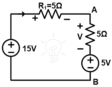
Now, we need to find the current passes through the loop. So, apply KVL to the above network.
15 – 5 = 5I + 5I
10 = 10I
I = 1A
So, the current passes through the element are the same as the original network. Now, find the voltage across all elements.
To find the voltage across 5Ω resister; we use Ohm’s law.
V5Ω = IR
V5Ω = 1 × 5
V5Ω = 5 V
Now, we find the voltage across the point A and B.
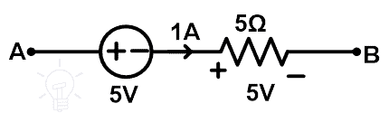
From the above figure, the current that passes through the 5Ω resister is 1A. So, the voltage across this element is 5V. And the total voltage between point A and B is
VAB = 5 + V5Ω
VAB = 5 + 5
VAB = +10V
Hence, after the substitution of the 10Ω resister branch with a 5Ω resister and 5V voltage source, the behavior of the network remains the same.
So, we can say that there is several methods available to find the substitution of the element of any network without changing the voltage and current of the element and without changing the behavior of the network.
- Related Post: Tellegen’s Theorem – Solved Examples & MATLAB Simulation
Steps to Solve Network Using Substitution Theorem
Step-1 Find the voltage and current of all elements of the network. Generally, the voltage and current can be calculated by the simple use of KCL, KVL, or Ohm’s law.
Step-2 Find the concerned branch, that you want to remove by a different element like current source, voltage source, or resistance.
Step-3 Find the appropriate value of substituted element provided that the voltage and current must not change.
Step-4 Verify the new circuit by calculating the voltage and current of all elements. And compare it with the original network.
This is all about the substitution theorem. Now, let’s take an example.
- Related Post: Maximum Power Transfer Theorem for AC & DC Circuits
Example & Solution of Substitution Theorem
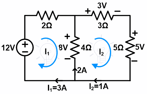
Solve the below network using the substitution theorem to calculate the current and voltage in all the resistors.

Step-1 Find the voltage and current of all elements. For that, in this example, we apply a KVL to the network.
Apply KVL at loop-1;
14 = 6I1 – 4I2 … (1)
Apply KVL at loop-2;
0 = 12I2 – 4I1
12I2 = 4I1
I1 = 3I2 … (2)
Put this value in the equation-1;
14 = 6(3I2) – 4I2
14 = 18I2 – 4I2
14 = 14I2
I2 = 1A
From equation-2;
I1 = 3A
Step-2 Now, we will remove the branches of loop-1 and make a single loop.
Step-3 We can put a voltage source or current source instead of the 4Ω resister. Here, we will put a current source.
The current that passes through loop-2 is 1A. Therefore, we replace the branch with a 1A current source. So, the remaining circuit is as shown in the below figure.

Step-4 Let’s verify the voltage and current of all elements.
This network has a single loop. And this loop has a current source. So, the value of current passes through the loop is the same as the value of the current source.
Here, the value of the current source is 1A. Hence, the current passes through the branch of 3Ω and 5Ω resister branch is 1A which is the same as the original network.
Now, find the voltage across 3Ω resister using Ohm’s law;
V3Ω = IR
V3Ω = 1 x 3
V3Ω = 3V
Now, find the voltage across 5Ω resister using Ohm’s law;
V5Ω = IR
V5Ω = 1 x 5
V5Ω = 5V
So, the voltage and current are the same as the original network. This is how the substitution theorem works.
Instead of the current source if we choose the voltage source in step-3. In this condition, the value of the voltage source is similar to the value of the 4Ω resister branch.
In the original network, the current passes through the 4Ω resister branch is;
I1 – I2 = 3 – 1 = 2A
According to Ohm’s law;
V4Ω = 2 x 4 = 8V
So, we need to connect the 8V voltage source with the network and the remaining circuit is as shown in the below figure.
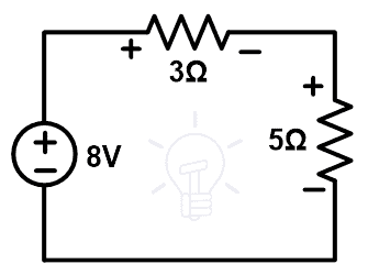
Step-4 Verify the voltage and current. Apply KVL to the above loop.
8 = 3I + 5I
8 = 8I
I = 8A
The voltage across 3Ω resister;
V3Ω = 1 × 3 = 3V
The voltage across 5Ω resister;
V5Ω = 1 × 5 = 5V
So, the voltage and current after substitution are the same as the original network.
Related Electric Circuit Analysis Tutorials:
- SUPERNODE Circuit Analysis – Step by Step with Solved Example
- SUPERMESH Circuit Analysis – Step by Step with Solved Example
- Kirchhoff’s Current & Voltage Law (KCL & KVL) | Solved Example
- Cramer’s Rule Calculator – 2 and 3 Equations System for Electric Circuits
- Wheatstone Bridge – Circuit, Working, Derivation and Applications
- Electrical and Electronics Engineering Calculators
- 5000+ Electrical and Electronic Engineering Formulas & Equations


