SUPERNODE Circuit Analysis | Step by Step with Solved Example
Supernode Analysis – Statement, Formula and Step by Step Solved Example
What is Supernode Analysis?
Today, we will try to answer the common question of why we use Supernode circuit analysis while we can simplify the circuit by simple Node or Nodal Circuit analysis.
In the previous article, we have discussed why we use supermesh circuit analysis instead of using simple mesh analysis for circuit simplification. If you got this point, then this is the same case about the discussion. If not satisfied, let me try to explain in the following example.
Consider both circuits in the following fig 1. Did you notice something different?
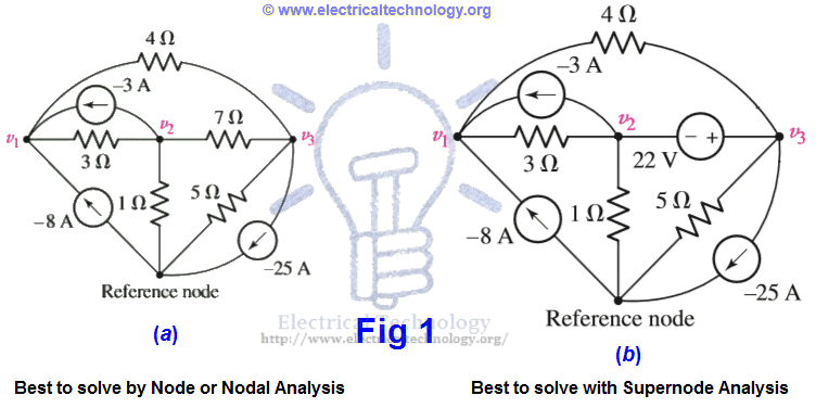
The difference in both circuits is that there is an additional voltage source of 22V instead of 7Ω resistor between node 2 and node 3. And this is the main point.
In Node or Nodal analysis, we apply the KCL (Kirchhoff’s Current Law) at each non-reference node i.e. we apply the simple KCL at once on three nodes in fig 1(a).
If we do the same i.e. apply the Nodal analysis instead of Supernode circuit analysis on the circuit in fig 1 (b), we face some difficulty at Node 1 and Node 2, because we don’t know what is the current in the branch with the voltage source? In addition, there is no such a way by which we adjust the situation i.e. we can’t express the current as a function of the voltage, where the definition of the voltage source is that the voltage is independent of the current. Due to these difficulties and troubles, we use supernode circuit analysis instead of Nodal analysis in the above fig 1 (b).
There are two methods to simplify the circuit in the above fig 1 (b).
The 1st one, which is more complex, is to assign an unknown current value to the branch containing the voltage source. Then apply KCL three times on the 3 Nodes (one KCL equation for each node). At last, apply KVL (Kirchhoff’s Voltage Law) which is v3 – v2 = 22V between Node 2 and Node 3. In this case, we get four (4) equations for unknown values in the above example, which is a little bit complex to simplify.
The 2nd method is easier than the above method which is called Supernode analysis. In this method, we treat Node2, Node3 and the voltage source of 22V together as a sort of Supernode and apply KCL to both nodes (Nod 2 and Node 3) at once.
The supernode is indicated by the region enclosed by the dotted line. This is possible because, if the total current leaving Node 2 is zero (0) and the total current leaving Node 3 is zero (0), then the total current leaving the combination is zero. This concept is shown in the following fig 2 (b) with the supernode (the area enclosed by the broken line).

Now, we will solve the circuit below by step by step supernode circuit analysis and then, we will summarize the whole supernode analysis (step by step).
Solved Example of Supernode Analysis
Example:
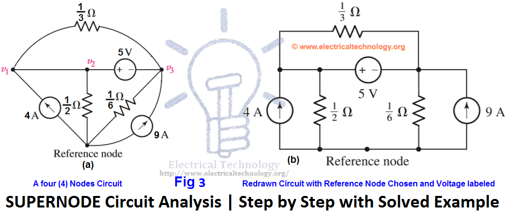
Use Supernode analysis to find voltage across each current source i.e. v1 & v2 in the following fig 3 (a)?
Solution:
First, we redraw the circuit as shown in fig 3(b)
We begin by writing a KCL equation for Node 1.
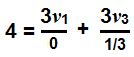
4 = 0 + 3v1 + 3v3 … → Eq 1.
Now, consider the supernode (Combination of Node1 and Node2). Moreover, one current source and three resistors are connected. Thus,
Apply KCL at Supernode (Node1 & Node2)
![]()
9 = 2v2 + 6v3 + 3v3 – 3v1 + 0.
9 = – 3v1 + 2v2 + 9v3 … → Eq 2.
Since we have three unknown values, therefore, we need one additional equation. Obliviously, we will go for the 5V voltage source between Nodes 2 and 3, which is;
v2 – v3 = 5 … → Eq 3.
Solving equations 1, 2 and 3 by Cramer’s rule or Cramer’s rule calculator, Elimination, Gauss Elimination or computer aided program such as MATLAB, we find,
- v3 = 0.575 V or 375mV.
- v2 = 5.375 V.
- v1 = 1.708 V.
Summary of Supernode Analysis (Step by Step)
- Redraw the circuit if possible.
- Count the Number of Nodes in the circuit.
- Design a Reference Node. This may be the node with the greatest number of branches. So that, we may minimize the number of of equations.
- Label the Nodal Voltages. Which are (N-1), where N= number of Nodes.
- Form a Supernode if the circuit or network contains voltage sources. This job is done by enclosing the source terminal, and other circuit element connected between the two terminals with the dotted line enclosure. This is shown in the above fig 2 (b).
- Write a KCL (Kirchhoff’s Current law) equation for each non-reference node as well as for each supernode which does not contain the reference node. On the first side, add the currents flowing into a supernode or node from the current sources. On the other hand, add the currents leaving the supernode or node through resistors. Take the “-“ sign in the account while writing KCL equations and solving the circuit.
- One KCL (Kirchhoff’s Current Law) is needed for each defined Supernode which can be accomplished by simple application of KCL. In simple words, relate the voltage across each voltage source to nodal voltages.
- If dependent sources appear in the circuit, In this case, express any additional unknown values and quantities like currents or voltages other than the Nodal voltages in terms of suitable nodal voltages.
- Arrange and organize the system of equations.
- At last, solve the system of equations for the Nodal voltages such as V1, V2, and V3 etc. there will be (N-1, where “N” = Number of Nodes) of them. If you find difficulties to solve the system of equations, refer to the above solved example.
- Related Posts:
- Thevenin’s Theorem. Step by Step Procedure with Solved Example
- Norton’s Theorem. Easy Step by Step Procedure with Example (Pictorial Views)
- Ohm’s Law: Simple Explanation with Statement and Formulas
- Maximum Power Transfer Theorem for AC & DC Circuits
- Kirchhoff’s Current & Voltage Law (KCL & KVL) | Solved Example
- Compensation Theorem – Proof, Explanation and Solved Examples
- Substitution Theorem – Step by Step Guide with Solved Example
- Millman’s Theorem – Analyzing AC & DC Circuits – Examples
- Superposition Theorem – Circuit Analysis with Solved Example
- Tellegen’s Theorem – Solved Examples & MATLAB Simulation
- Voltage Divider Rule (VDR) – Solved Examples for R, L and C Circuits
- Current Divider Rule (CDR) – Solved Examples for AC and DC Circuits
- Star to Delta & Delta to Star Conversion. Y-Δ Transformation


Great job!
The answer to v1 is not correct v1=v2.
Yes, This is Not correct …..
Yes incorrect
Please number the nodes assign nos and alphabets to nodes and corners. Many a times you said loop 1 but where is loop 1, it can be the right loop or the left one. Readers have to figure this out by seeing and understanding the equation which can be difficult sometimes as we don’t know the concepts correctly(that’s why readers are here)
v1 = 1.12 v2= 5.21 v3= 0.21 my calculator said that
first equation is wrong, 4=(v1-v3)/9/(1/3)
v1 and v2 are the same node. The supernode encompasses the 1/3 ohm resistor. So it shouldn’t be in any KCL equations. Also the problem is only a system of two linear independent equations.
v2 – v3 =5 is supernode and v1=v2
Now the supernode include all the nodes so you just right one KCL for the currents in/out of it:
v2-0/(1/2) + v3-0/(1/6) – 9 – 4 = 0
thus
v1=v2=5.375 V
v3=.375 V
Yes. you are right.
first eqn must be 4=3V1-3V3
Am I saying it wrong pls correct me if I do?