Current Divider Rule (CDR) – Solved Examples for AC and DC Circuits
Current Division “CDR” for for Resistive, Inductive and Capacitive Circuits
What is Current Divider Rule (CDR)?
When a number of elements are connected in parallel, the current divides into a number of parallel paths. And the voltage is the same for all elements which are equal to the source voltage.
In other words, when the current passes through more than one parallel path (the voltage divider rule “VDR” or voltage division is used to calculate the voltage in the series circuits), the current divide in each path. The value of current passes through a particular branch depends on the impedance of that branch.
The current divider rule or current division rule is the most important formula that is widely used to solve circuits. We can find the current that passes through each branch if we know the impedance of each branch and the total current.
The current always flows through the least impedance. So, the current has an inverse relationship with impedance. According to ohm’s law, the current that enters the node will be split between them in inverse proportion to the impedance.
It means that the smaller value impedance has a larger current as the current chose the least resistance path. And the larger value resistance has the least current.
According to the circuit elements, the current divider rule may describe resistors, inductors, and capacitors.
Related Posts:
- Current Divider Rule Calculator – CDR Formula & Calculations
- Voltage & Current Divider Rules (VDR & CDR) Equations
Current Divider Rule for Resistive Circuits
To understand the resistive current divider rule, let’s take a circuit in which the resistors are connected in parallel. The circuit diagram is shown in the figure below.
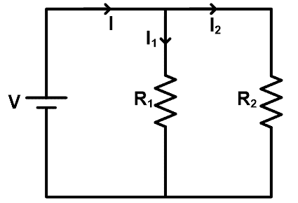
In this example, a DC source supply to all resisters. The voltage of resisters is the same as the source voltage. But due to parallel connection, the current divides into different paths. The current divides at each node and the value of current depend on the resistance.
We can directly find the value of current passing through each resistor with the help of the current divider rule.
In this example, the main current supplied by the source is I. And it divides into two resistors R1 and R2. The current passes through the resistor R1 is I1 and the current passes through the resistor R2 is I2.
As the resistors are connected in parallel. So, the equivalent resistance is Req.
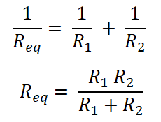
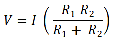
Now, according to Ohm’s law;
V = I Req
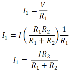
Both resisters are connected in parallel with a DC source. Therefore, the voltage across the resistor is the same as the source voltage. And the current that passes through the resistor R1 is I1.
So, for resister R1;
Similarly, for resister R2;
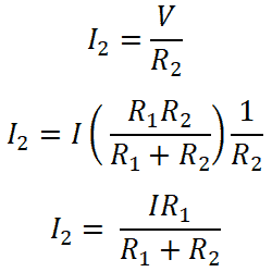
So, these equation shows a current divider rule for resistance connected in parallel. From these equations, we can say that the current that passes through resister is equal to the ratio of multiplication of total current and opposite resistance with the total resistance.
Related Posts:
- Thevenin’s Theorem. Step by Step Guide with Solved Example
- Norton’s Theorem. Step by Step Guide with Solved Example
Current Divider Rule for Inductive Circuits
When inductors are connected in parallel, we can apply the current divider rule to find the current that passes through each inductor. To understand the current divider rule, we take a circuit in which the inductors are connected in parallel as shown in the figure below.
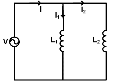
Here, two inductors (L1 and L2) are connected in parallel with a source voltage V. Total current passes through the source is I ampere. The current passes through the inductor L1 is I1 and the current passes through the inductor L2 is I2.
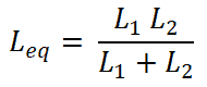
Now, we need to find the equations for current I1 and I2. For that, we will find the equivalent inductance Leq;
We know that the total current passes through the circuit are I and it is equating as;
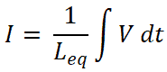
So,

Now, for inductor L1, current passes through this inductor is I1;

For inductor L2;
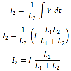
The current divider rule for the inductor is the same as the current divider rule for the resistors.
Related Posts:
- Superposition Theorem – Circuit Analysis with Solved Example
- Maximum Power Transfer Theorem for AC & DC Circuits
Current Divider Rule for Capacitive Circuits
When the capacitors are connected in parallel, we can find the current passes through each capacitor by using the current divider rule. To understand the current divider rule for the capacitor, we take an example in which the capacitors are connected in parallel as shown in the figure below.

Here, two capacitors (C1 and C2) are connected in parallel with a voltage source V. The current passes through the capacitor C1 is I1, and the current passes through the capacitor C2 is I2. The total current supplied through the source is I.
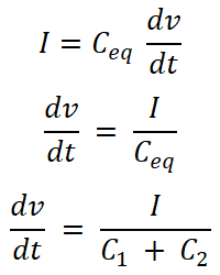
Now, we need to find the equations for current I1 and I2. For that, we will find the equivalent capacitance Ceq;
Ceq = C1 + C2
We know the equation for the current that passes through the capacitor. And the equation for the total current supplied by the source is;
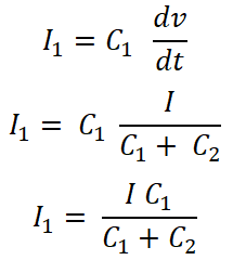
For capacitor C1, the current that passes through this capacitor is I1;
For Capacitor C2;
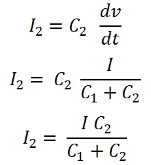
The current divider rule for the capacitor is slightly different from the current divider rule for the inductor and resistor.
In the capacitor current divider rule, the current passes through a capacitor is a ratio of the total current multiplied by that capacitor to the total capacitance.
Related Posts:
- Millman’s Theorem – Analyzing AC & DC Circuits – Examples
- Tellegen’s Theorem – Solved Examples & MATLAB Simulation
Solved Examples for AC and DC Circuits using CDR
Current Diver Rule for DC Circuit
Example:1
Find the current passes through each resistor by the current divider rule for the given network.
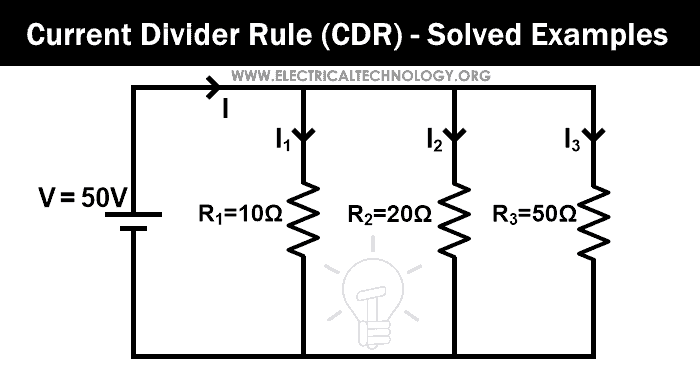
In this example, three resistors are connected in parallel. First, we find the equivalent resistance.
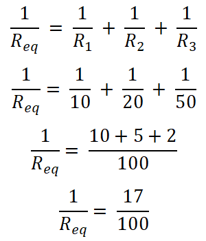
Req = 100/17
Req = 5.882 Ω
The total current supplied by the source is I. So, according to ohm’s law;
V = I Req
50V = I (5.882Ω)
I = 50V / 5.882Ω
I = 8.5 A
Now, we apply the current divider rule to the first resister (10 Ω), and the current passes through this resister is I1;
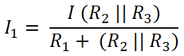
Here R2 and R3 are connected in parallel. So, we need to find the equivalent resistance between R2 and R3.
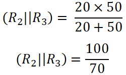
(R2 || R3 ) = 14.285 Ω
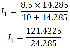
I1 = 4.9999 ≈ 5 A
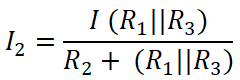
Similarly, we apply the current divider rule to the Second resistor (20 Ω), and the current that passes through this resister is I2;
Here,
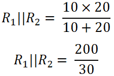
(R1 || R3 ) = 8.33 Ω
I2 = 2.499 ≈ 2.5 A
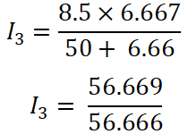
Now, we apply the current divider rule to the third resistor (50 Ω), and the current that passes through this resistor is I3.
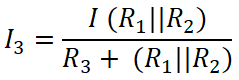
Here,
(R1 || R2 ) = 6.66 Ω
I3 = 1.00 A
So, the summation of all three currents will be;
I1 + I2 + I3 = 5 + 2.5 + 1 = 8.5 A
And this current is the same as the total current supplied by the source.
Related Posts:
- Voltage Divider Rule (VDR) – Solved Examples for R, L and C Circuits
- Voltage Divider “VDR” Calculator, Examples & Applications
Current Diver Rule for AC Circuit
Example-2
Consider an AC circuit having a resistor and capacitor connected in parallel as shown in the figure below. Find the current passes through the resistor and capacitor using the current divider rule. Consider 60 Hz frequency.
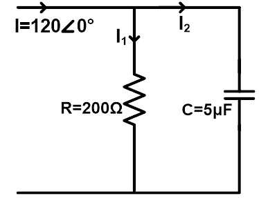
ZR = 200 Ω = 200∠0°Ω
ZC = 1/(2 πfC) = 1/(2 π 60(5×10⁶) )
ZC = 106 / (600 π)
ZC = 530.78 ∠-90° Ω
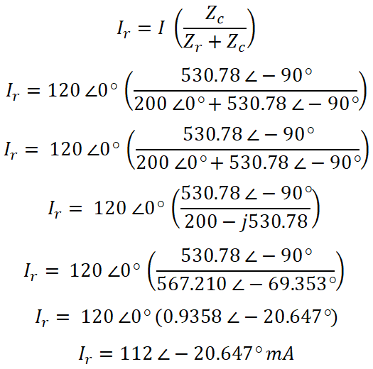
Now, according to the current divider rule, the equation of current passes through the resistor is;
Now, similarly, we can find the current passes through the capacitor. According to the current divider rule, the equation of current passes through the capacitor is;
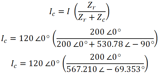
IC = 120 ∠0° (0.3526 ∠ 69.353°)
IC = 42.31 ∠ 69.353°
If you want to prove this answer, you can add both currents. And the value of this current is the same as the source current.
Related Electric Circuit Analysis Tutorials:
- Compensation Theorem – Proof, Explanation and Solved Examples
- Substitution Theorem – Step by Step Guide with Solved Example
- SUPERNODE Circuit Analysis – Step by Step with Solved Example
- SUPERMESH Circuit Analysis – Step by Step with Solved Example
- Kirchhoff’s Current & Voltage Law (KCL & KVL) | Solved Example
- Cramer’s Rule Calculator – 2 and 3 Equations System for Electric Circuits
- Wheatstone Bridge – Circuit, Working, Derivation and Applications
- Electrical and Electronics Engineering Calculators
- 5000+ Electrical and Electronic Engineering Formulas & Equations


