Maximum Power Transfer Theorem for AC and DC Circuits
Maximum Power Transfer Theorem for AC & DC Circuits – Solved Examples
Introduction to Maximum Power Transfer Theorem
Very often we come across various real time circuits that works based on maximum power transfer theorem. For effective way of connecting source to load, an impedance matching transformer is used. In case of transmission lines, the distortion and reflections are avoided by making source and load impedances to be matched to the characteristic impedance of the line. 
In case of solar photovoltaic (PV) systems, Maximum Power Point Tracking (MPPT) is achieved with incremental conductance method (ICM) in which the load resistance must be equal to the output resistance of the PV panel and Solar Cell
So there are several cases or applications that use maximum power transfer theorem for effectively connecting the source to a load. This theorem can be applied for both DC and AC circuits. Let us discuss this theorem for DC as well AC circuits with examples.
Maximum Power Transfer Theorem for DC Circuits
This theorem describes the condition for maximum power transfer from an active network to an external load resistance. It states that in a linear, active, bilateral DC network, the maximum power will be transferred from source to the load when the external load resistance equals to the internal resistance of the source.
This theorem can be developed with reference to practical current or voltage source.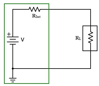
If the source is a practical or independent voltage source, its internal series resistance must match with load resistance to deliver maximum power. In case of practical or independent current source, parallel internal resistance should match with load resistance.
In the above circuit internal source series resistance alters the power delivered to the load and hence the maximum current delivered from the source to the load is limited.
Explanation of Maximum Power Transfer Theorem
Let us consider the electrical system with load as shown below, to which we are going to determine the value of load resistance so as to deliver the maximum power to the load.
Basically, the condition at which maximum power transfer can be obtained by deriving an expression of power absorbed by the load using mesh or nodal current techniques and then finding its derivative with respect to the load resistance.
In below figure, electrical system may be a complex circuit consisting of several elements and sources. In such case finding of maximum power transfer condition can be tedious.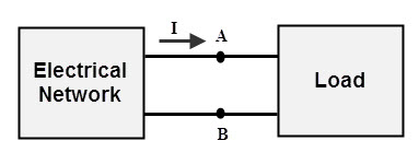
Alternatively we can find the maximum power transfer with the use of Thevenin’s equivalent circuit (Read Here the step by step Thevenin’s Theorem with solved examples). Now we will replace the electrical system which we are considered as complex part with its Thevenin’s equivalent circuit as shown in below.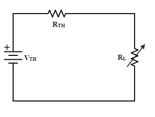
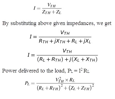
From the above circuit, the current flowing through the load, ‘I’ is given as
In the above equation RL is a variable, therefore the condition for maximum power delivered to the load is determined by differentiating load power with respect to the load resistance and equating it to zero.
This is the condition for maximum power transfer, which states that power delivered to the load is maximum, when the load resistance RL matches with Thevenin’s resistance RTH of the network.
Under this condition, power transfer to the load is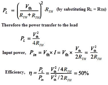
The above equation shows that the efficiency is 50% under maximum power transfer condition. Due to this 50 percent efficiency, maximum power transfer is not always desirable. For a given values the Thevenin’s voltage and Thevenin’s resistance, the variation of power delivered to the load with varying load resistance is shown in below figure.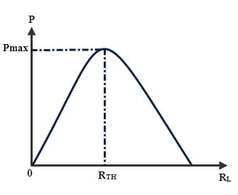
Solved Example on Maximum Power Transfer Theorem in DC Circuits
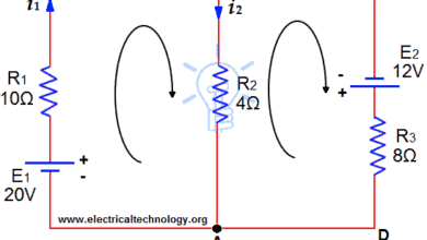
Consider the below circuit for which we are going to determine the value of load resistance, RL for which maximum power will transfer from source to load.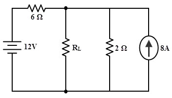
Now, the given circuit can be further simplified by converting the current source into equivalent voltage source as follows. We need to find the Thevenin’s equivalent voltage Vth and Thevenin’s equivalent resistance Rth across the load terminals in order to get the condition for maximum power transfer. By disconnecting the load resistance, the open-circuit voltage across the load terminals can be calculated as;
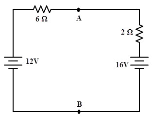
By applying Kirchhoff’s voltage law, we get
12 – 6I – 2I – 16 = 0
– 8I = 4
I = –0.5 A
The open-circuit voltage across the terminals A and B, VAB = 16 – 2 ×0.5
= 15 V
Thevenin’s equivalent resistance across the terminals A and B is obtained by short-circuiting the voltage sources as shown in the figure.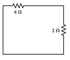
Req = (6 × 2) / (6 + 2)
= 1.5 Ω
So the maximum power will transferred to the load when RL = 1.5 ohm.
Current through the circuit, I = 15 / (1.5 + 1.5)
= 5 A
Therefore, the maximum power = 52 × 1.5 = 37.5 W
Maximum Power Transfer Theorem for AC circuits
This theorem gives the impedance conditions in AC circuit for maximum power transfer to a load. It states that in an active AC network consisting of source with internal impedance ZS which is connected to a load ZL, the maximum power transfer occurs from source to load when the load impedance is equal to the complex conjugate of source impedance ZS.
Explanation & Proof of the Maximum Power Transfer Theorem
Consider the below circuit consisting of Thevenin’s voltage source with series Thevenin’s equivalent resistance (which are actually replacing the complex part of the circuit) connected across the complex load.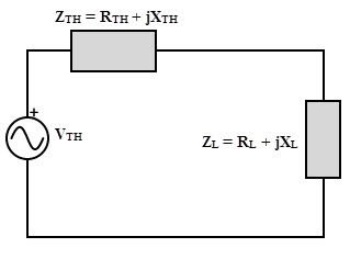 From the above figure, Let ZL = RL + jXL and ZTH = RTH + jXTH then the current through the circuit is given as,
 For power to be maximized, the above equation must be differentiated with respect to XL and equates it to zero. Then we get
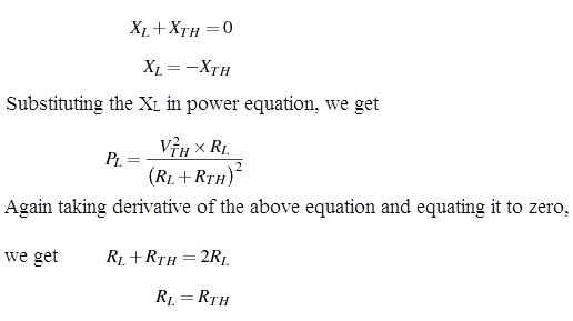
Again taking derivative of the above equation and equating it to zero, we get
RL+ RTH = 2 RL
RL = RTH
Therefore, in AC circuits, if XL = – XTH and RL = RTH, maximum power transfer takes place from source to load. This implies that maximum power transfer occurs when the impedance of the load is complex conjugate of the source impedance, i.e., ZL = Z*TH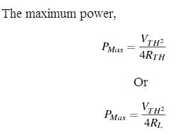
Solved Example on Maximum Power Transfer Theorem in AC Circuits
Consider the below AC network to which we are going to determine the condition for maximum power transfer and the value of maximum power.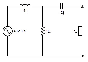
For finding out the maximum power transfer, first we have to determine Thevenin’s voltage and equivalent resistance. By disconnecting the load impedance and making the voltage source short-circuit, the network becomes as shown below.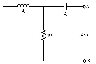
Then, ZAB = ((4 × 4j)/ (4 + 4j)) – 2j
= (4j – 2j (1+ j)) / (1+ j)
= 2 Ω
Therefore, the condition for maximum power transfer is ZL = ZTH = 2 Ω
The Thevenin’s voltage of the circuit can be determined by applying the voltage divider rule to the below circuit.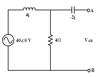
VTH = VAB = (40 / 4 (1+j)) × 4
= 28.29∠-450
Then maximum power, Pmax = VTH2/ 4RTH
= 800/ 4 = 100 W
Applications of Maximum Power Transfer Theorem
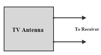
- In electronic circuits, especially in communication system the signal present at the receiving antenna is of low strength. In order to receive the maximum signal from the antenna, impedance of (TV) receiver and (TV) antenna should be matched.

- In an audio amplifier with audio speaker arrangement in public addressing systems, speaker resistance must be equal to the amplifier resistance in order to transfer maximum power from amplifier to the speaker.

- In case of a car engine starting system, starter motor resistance must be matched with internal resistance of the battery. If the battery if full and these resistances are matched, maximum power will be transferred to the motor to turn ON the engine.

Good to Know:
Summary of Maximum Power Transfer Theorem
- Maximum power transfer theorem can be applied to both DC and AC circuits, but the only difference is that the resistance is replaced with impedance in AC circuit.
- In an AC electrical network the maximum power will be transferred from source section to the load section when the impedance of the load is complex conjugate of the source impedance.
- It is important to note that in AC circuit, source also possesses an internal reactance. Therefore in order to have maximum power transfer the load must possess same value of reactance but it should be of opposite type. This means that the load must have an equivalent capacitive reactance, if source has inductive reactance, and vice versa.
- The efficiency is 50 percent only at maximum power transfer condition. So in power system network, this condition causes a large voltage drop in the lines. But the goal of the power system network is to increase the efficiency rather than maximum power. Therefore, power system never operated under maximum power transfer.
- Related Posts:
- Thevenin’s Theorem. Step by Step Procedure with Solved Example
- Norton’s Theorem. Easy Step by Step Procedure with Example (Pictorial Views)
- SUPERNODE Circuit Analysis | Step by Step with Solved Example
- SUPERMESH Circuit Analysis | Step by Step with Solved Example
- Maximum Power Transfer Theorem for AC & DC Circuits
- Kirchhoff’s Current & Voltage Law (KCL & KVL) | Solved Example
- Compensation Theorem – Proof, Explanation and Solved Examples
- Substitution Theorem – Step by Step Guide with Solved Example
- Millman’s Theorem – Analyzing AC & DC Circuits – Examples
- Superposition Theorem – Circuit Analysis with Solved Example
- Tellegen’s Theorem – Solved Examples & MATLAB Simulation
- Voltage Divider Rule (VDR) – Solved Examples for R, L and C Circuits
- Current Divider Rule (CDR) – Solved Examples for AC and DC Circuits
- Star to Delta & Delta to Star Conversion. Y-Δ Transformation
- Ohm’s Law: Simple Explanation with Statement and Formulas
- Oersted’s Law of a Magnetic Field of a Straight Current Carrying Conductor
- Right Hand Grip/Thumb Rule, Corkscrew Rule & End/Clock Rule


Peace
I’m khaled
Resident in Saudi Arabia
Assistant possible
I have no problem with the welder Made in China
The problem is
Capacitive electricity is 60Hz
The welding machine is 50Hz
After examination problem in Board
Is it possible Assistant
solve a resistors r1=10,diode is in forward bias ,r2=5,r3=10,find rL?,when voltage is 100v.
A.c. Drive repair
can u plz provide the condition for this theorm
in the graph showing the variation of power delivered to the load with varying load resistance, shouldnt power TEND to zero when load resistance approaches infinity?
The solved example clear my confusion. Thank you