Types of Electrical Drawings and Wiring Circuit Diagrams
How to Read Different Types of Electrical Diagrams and Drawings
In Electrical and Electronics Engineering, we use different types of drawings or diagrams to represent a certain electrical system or circuit. These electrical circuits are represented by lines to represent wires and symbols or icons to represent electrical and electronic components. It helps in better understanding the connection between different components. Electricians rely on electrical floor plan (which is also an electrical diagram) for doing any building wiring.

Engineers use various types of electrical drawings to highlight certain aspects of the system but the physical circuit and its function still remains the same. Some of these electrical drawings or diagrams have been described below.
Related Posts:
- Top & Best Books & Guides for Electricians and Apprentices
- Types of Motor Starters and Motor Starting Methods
Block Diagram
A block diagram is a type of electrical drawings that represents the principle components of a complex system in the form of blocks interconnected by lines that represent their relation. It is the simplest form of electrical drawings as it only highlights the function of each component and provides the flow of process in the system.
Block diagram are easier to design and is the first stage in designing a complex circuit for any project. It lacks the information about the wiring and placement of individual components. It only represents the main components of the system and ignores any small components. This is why; electricians do not rely on block diagram.
Example:
The following two examples of block diagram show an FM transmitter and a variable frequency driver VFD.

This diagram shows the process of converting an audio signal into frequency modulated signal. It is pretty simple and easy to understand. Each block process the signal and pass it to the next one. Practically, the FM transmitter does not look like this, because the block diagram omits the individual components.
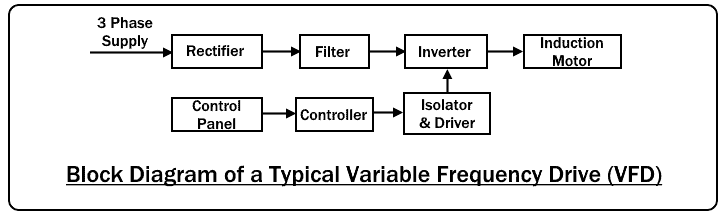
This block diagram shows a 3 phase AC power supply conversion into a DC which is again converted into a controlled AC supply. It is quite a complicated process but this diagram simplifies the process into blocks for better understanding.
The block diagram provides an idea how the process is done by not delving too deep into the electrical terms but it is not enough to implement a circuit. Each block is a complicated circuit that can be explained using other drawings techniques described below.
- Related Post: Types of Fire Alarm Systems and Their Wiring Diagrams
Power Diagram
A power wiring diagram, also known as an electrical power distribution diagram, is a schematic representation of an electrical system that specifically focuses on illustrating the distribution of electrical power within a facility, a complex electrical network or specific electrical circuit.
It typically shows the connections and routes of power supply, including transformers, circuit breakers, contactors, motors, switches, and distribution panels. Power wiring diagrams are crucial in ensuring the safe and efficient distribution of electricity, as they help engineers, electricians, and maintenance personnel understand the layout of power circuits, voltage levels, and load distribution.
These diagrams aid in planning, troubleshooting, and maintenance of electrical systems, helping to prevent electrical hazards and optimize power distribution for various applications, from residential buildings to industrial facilities.
Example:
The following power diagram shows the ON and OFF control of a 3-Phase Motor using Direct online DOL Starter.

Control Wiring Diagram
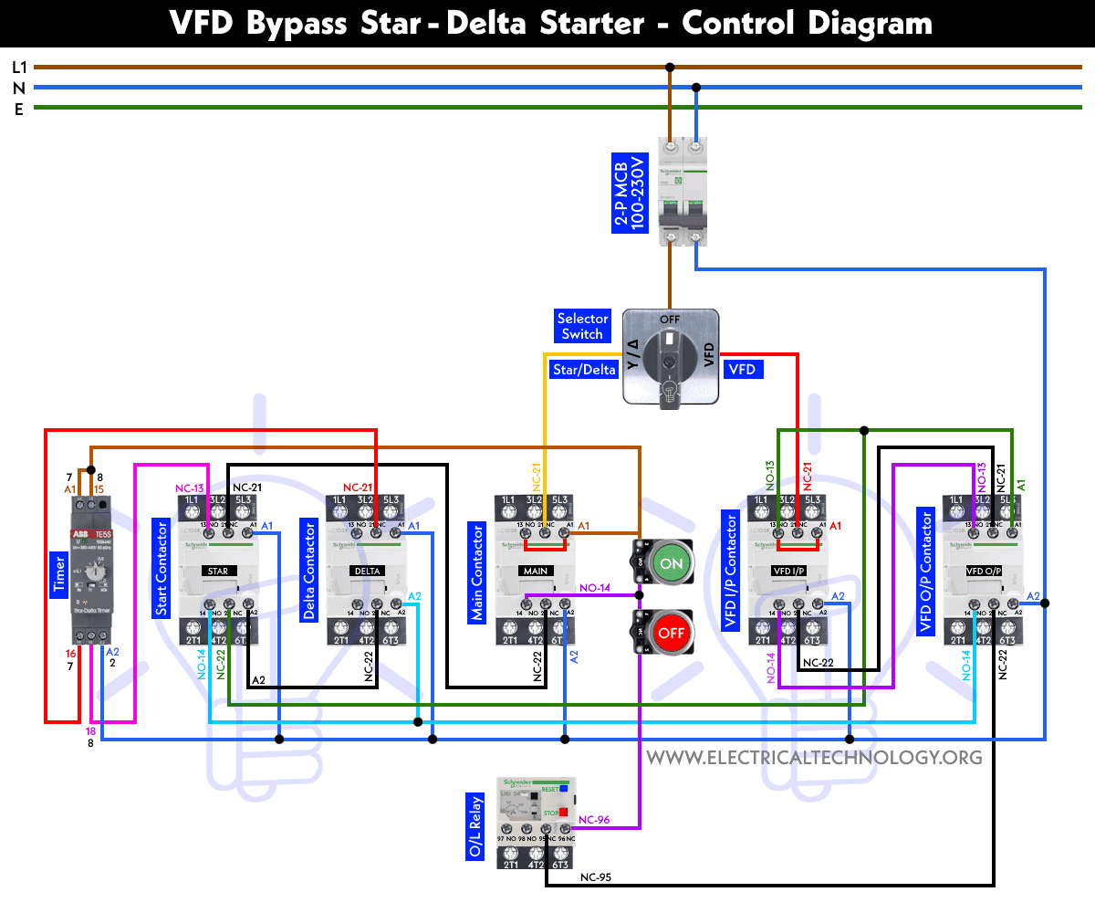
Control wiring diagram shows the actual components used with proper wiring connection which is further used to control the operation of the power wiring to the connected machinery. Sometimes, power diagram is also added to the control wiring for better illustration.
Example:
The following control wiring diagram shows bypassing a VFD and run the motor manually via Star-Delta starter.
Control Circuit Diagram
A control circuit diagram is nothing special drawings but the symbols of different components arranged and control by the single phase power supply designed to control the 1-phase or 3-phase power circuit.
Example:
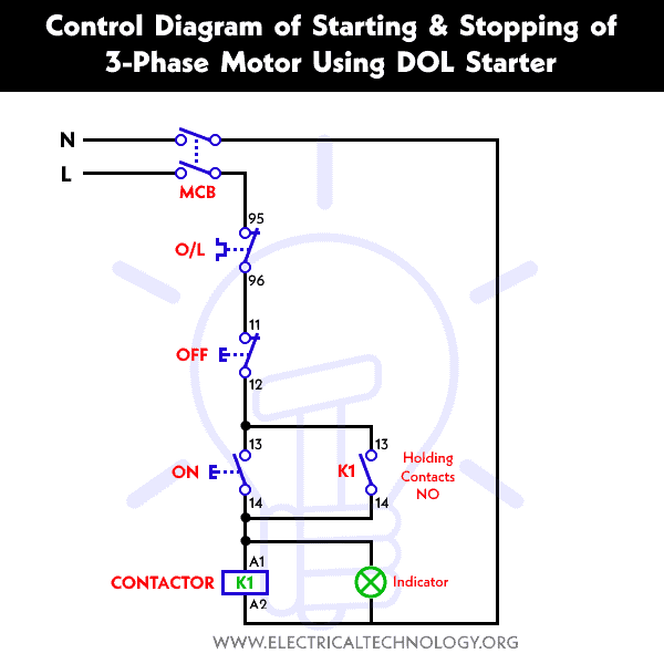
The following control circuit diagram shows the ON and OFF operation of a three-phase induction motor using DOL starter.
Schematics Circuit Diagram
The schematic diagram of an electrical circuit shows the complete electrical connections between components using their symbols and lines. Unlike wiring diagram, it does not specify the real location of the components, the line between the components does not represent real distance between them.
it helps in showing the series and parallel connection between the components and the exact terminal connection between them. One can easily troubleshoot certain schematic by applying electronic circuit theory.
It is the most common type of electrical drawings and are mostly used in implementing electrical circuits by technician. Most engineering student rely of schematic diagram while developing various electrical projects.
Example:

This is a schematic diagram of a voltage amplifier. It uses various symbols to represents the electrical components and the lines to represent the electrical connection between their terminals. The practical circuit may vary in appearance but the electrical connection and its function will remain the same.
- Related Post: Types of Transformers and Their Applications
Schematics Wiring Connection Diagram
A schematic wiring diagram is a visual representation of an electrical or electronic circuit that uses symbols and lines to depict the components and their interconnections. Unlike a physical layout diagram, a schematic focuses on the logical arrangement and functioning of the components within a circuit, making it a valuable tool for engineers, technicians, and electricians to understand and troubleshoot complex systems.
Symbols and actual components in a schematic diagram represent various elements like circuit breakers, contactors, resistors, capacitors, transistors, wires, and connections, allowing for a concise and standardized way to convey circuit information. Schematic diagrams are crucial in designing, analyzing, and repairing electrical and electronic systems, providing a clear and abstracted view of how a circuit operates without the need for a detailed physical representation.
Example:
The following schematic wiring connection diagram shows a three-phase motor is controlled by two power supply where both contactors are electrically interlocked. Hence, only one contactor may be operational at a time.
Wiring Installation Diagram
The wiring diagram is used for the representation of electrical components in their approximate physical location using their specific symbols and their interconnections using lines. Vertical and horizontal lines are used to represent wires and each line represents a single wire that connects between electrical components.
Wiring diagram shows a pictorial view of the components such that it resembles its electrical connection, arrangement and position in real circuit. It really helps in showing the interconnections in different equipment such as electrical panel and distribution boxes etc. they are mostly used for wiring installation in home and industries.
Example:
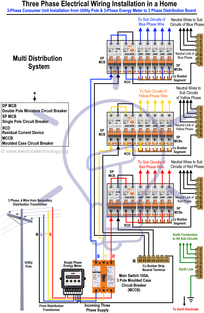
This is a wiring diagram of a three phase wiring installation in a home. It clearly shows the components with its proper electrical connection. Each individual line (with color code) represents a specific phase wire and its connection with each component. Such type of diagrams is used for wiring installation by electricians in home.
- Related Post: Types of Batteries and Cells and Their Applications
Pictorial Diagram
The pictorial diagram does not necessarily represent the actual circuit but shows drawings only. In fact it shows the visual appearance of the circuit in real time. it cannot be used to understand or troubleshoot the actual circuit and for this reason alone, it is not commonly used. For someone with less knowledge of electrical, it is impossible to understand how the circuit works and diagnose it.
Example:
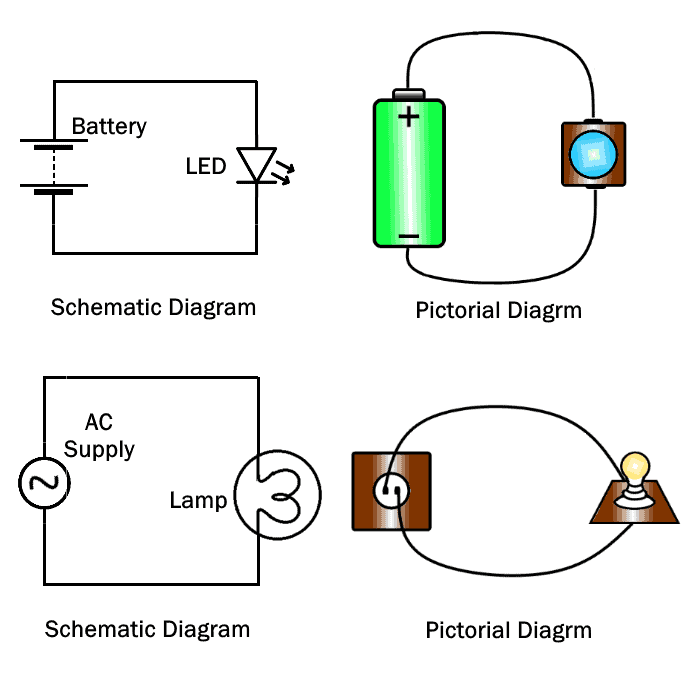
As you can see, the pictorial diagram does not provide enough information regarding the electrical connection of the components.
Related Posts:
Single Line Diagram or One-line Diagram
Single Line diagram (SLD) or one-line diagram is the representation of an electrical circuit using a single line. As the name suggests, a single line is used to denote the multiple power lines such as in 3 phase system.
Single line diagram does not show the electrical connections of the component but it may show the size and ratings of the components being used. it simplify complex 3 phase power circuits by showing all the electrical components and their interconnection.
They are used for determining and isolating any faulty equipment in any power system during troubleshooting.
The SLD diagram uses dedicated electrical symbols and icon for different components.
Example:
A common example of a 3 phase power circuit to represent using a single line diagram would be the power transmission and distribution to the consumers.
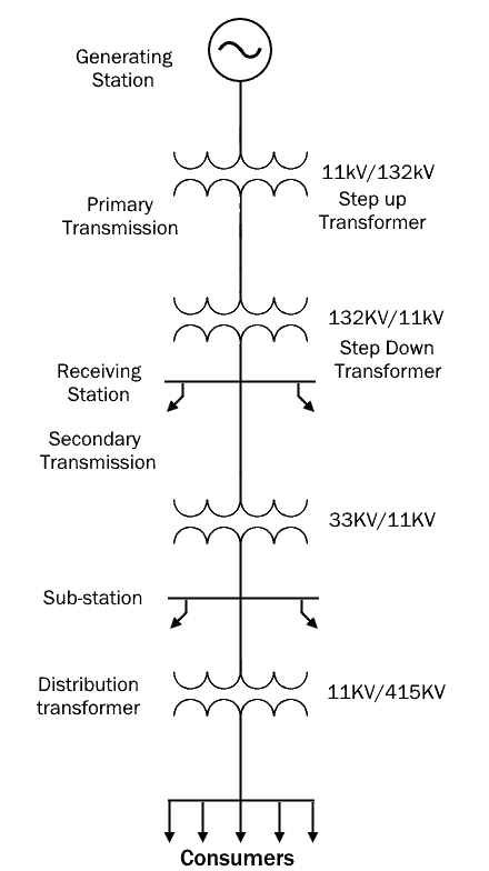
This diagram clearly shows a 3 phase power generating station that transmits the power to the consumers below. It passes through multiple stations, whose function and ratings are also mentioned but their electrical connections are not highlighted.
Related Posts:
Ladder Diagram or Line Diagram
Ladder diagram are electrical diagrams that represents an electrical circuits in industries to document control logic systems. It resemble a ladder which is why it is named ladder diagram. There are two vertical lines; the left vertical line represents power rail (voltage source) while the right vertical line represents the ground or neutral. Each horizontal row represents a parallel circuit called rung.
A ladder diagram is simple, easier to understand and helps in troubleshooting the circuit quickly.
Example:

Logic Diagram
Logic diagram represents a logic circuit by showing complex circuit and process using various blocks or symbols. The logic functions are represented by their logic symbols whereas the blocks are used to represent complex logic circuit. These blocks are labeled with their logic function for better understanding without knowing the internal structure.
The blocks are interconnected by lines which represent the input and output lines for the signals.
The logic diagram does not show the electrical characteristics of a circuit such as current, voltage or power etc. it only represents the logical function of the circuit or device where the signal is considered in binary format i.e. 1 or 0. Logic diagram are commonly used in digital logic designing.
Example:

This is the logic diagram of a single bit full adder made from digital logic gates. Each input lines A and B feeds a single bit to the adder while c in represents a carry bit from previous adders. The output lines provide the sum and carry out in form of bits.
- Related Post: Different Types of Sensors with Applications
Riser Diagram
The riser diagram is the illustration of the physical layout of electrical distribution in a multilevel building using a single line. It shows the size of conduits, wire size, circuit breaker rating and other electrical devices (rating of switches, plugs, outlets etc.) from the point of entry up to the small circuit branches on each level. It shares the layout with alarm system as well as telecom and internet cables.
The riser diagram got its name because it illustrates the power flow from one level to another. It does not specify the physical location of the equipment and does not contain unnecessary information.
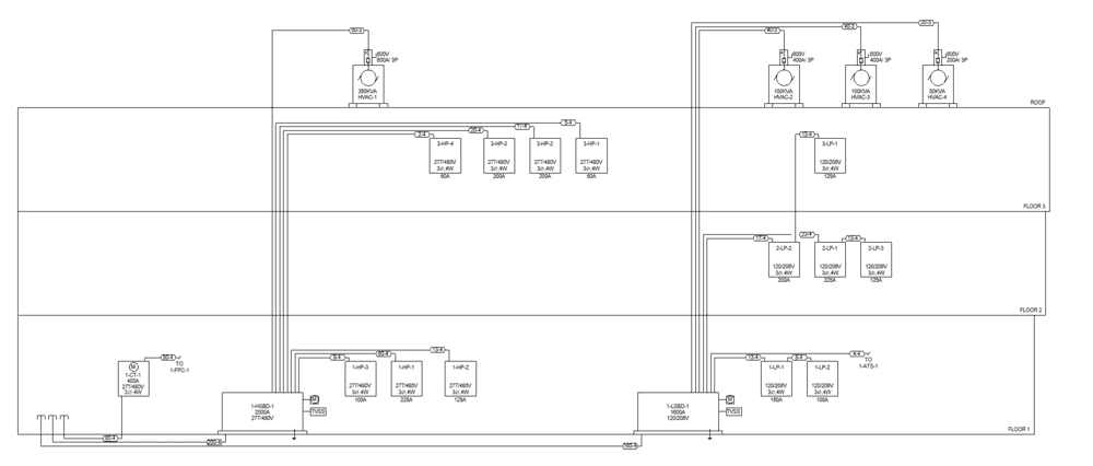
It mainly focuses on the power distribution to the different appliances in a building on each level. It provides information how the lighting, heating and ventilation etc. in the building works and if there is any sort of hazard, it can be easily rectified.
Electrical engineers rely on riser diagram of a building to avoid any potential electrical hazards.
Related Posts:
Electrical Floor Plan
It is a vertical representation of various appliances such as light, switch and fans etc. in a building. It specifies their exact location with their size and distance from each wall and ceiling. It shows scaled version of each room from above. It usually contains legend that provides a visual explanation of the symbols used in it.
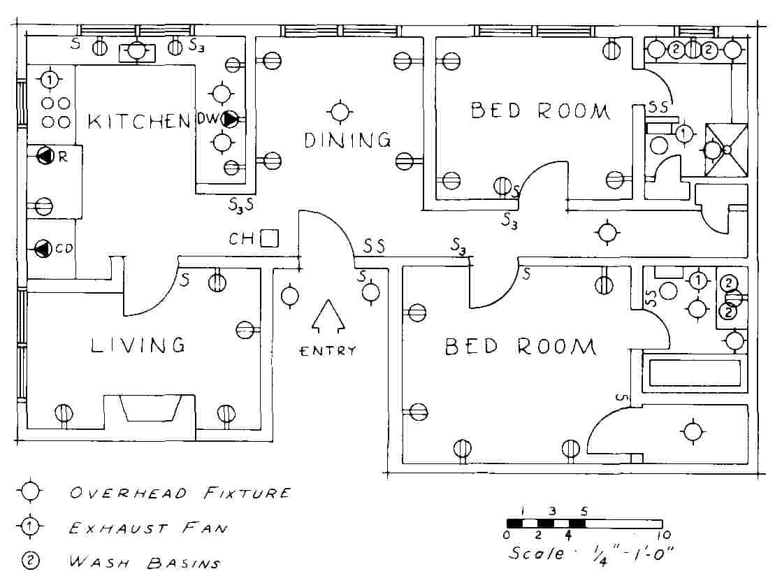
Individual Floor plan is designed for each floor in a multi-level building and it is used by electrical for wiring in a newly constructed building or during the rewiring of a building. it helps in locating the cables layout inside the walls.
Click image or open in a new tab to enlarge

Related Posts:
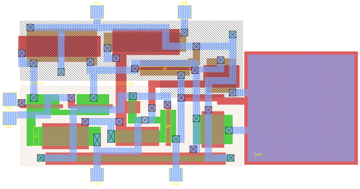
IC Layout Diagram
The IC layout diagram or IC (mask) layout refers to the internal design of a semiconductor component especially drawings in PCB design. It is made up of multiple layers or masks of metal, oxide and semiconductor material to form an Integrated circuit (IC). It represents the geometry as well as the size of different semiconductor layer and their connection. It describes the internal structure and are used in manufacturing and designing Integrated circuits.
Related Posts:
- Types of Electrical Wires and Cables
- Types of Electrical and Electronics Symbols
- Types of Motor Starters and Motor Starting Methods
- Types of Wiring Systems and Methods of Electrical Wiring
- Types and Methods of of Earthing & Grounding
- Basic Electrical / Electronic Symbols
- All Electrical and Electronic Symbols
- Electrical and Electronic Engineering Formulas & Equations
- 800+ Electrical & Electronic Abbreviations with Full Forms. A-Z
- Top Must Have Android Apps for Electrical & Electronics Engineers & Students
- Top iOS Apps for Electrical & Electronics Engineers & Students
- Electrical and Electronics Engineering Calculators
- Electrical Wiring Color Codes for AC & DC – NEC & IEC


Hallo,
Under “Circuit Diagrams Circuit Diagram” there is a Transistor stage with errors in it. There should be a dot on the “intersection” on the left, it is a connection. The input capacitor (of 17 uF?) Is drawn with the wrong polarity. Both base resistors have an unnecessarily low value, why?
Vr. groet,
mees Kees
Check the single line diagram for the power distribution circuit. The 33/11KV transformer is not required. The voltage ratios are incorrect
Expected more information
SLD of distribution of single phase 1kw load to 30flat from a 100kva 3phase dg set
Thanks for the useful resources !