Electric Stress Control in Cable, Joints & Terminations
How to Control Electric Stress in Cable Joints & Terminations?
Introduction
Power cables are of great importance in power transmission and distribution systems.
Terminations and joints are the basic accessories of the power cables and they are required to make connections between lines or to an electrical apparatus.
The various aspects are considered while designing the cable terminations and joints because they must possess the same integrity as their associated cables while making the connection both all indoor and outdoor applications.
The most critical aspect of high voltage cable jointing and termination is control of the dielectric stress originated at the point of screen termination–electric stress control.
Electrical Stress & Stress Control
Terminals and joints of high and medium voltage cables must manage the electric fields at the ends. When the insulation shield is removed from a cable, high potential gradients are concentrated at the cutback point, as show in the Figure 1.
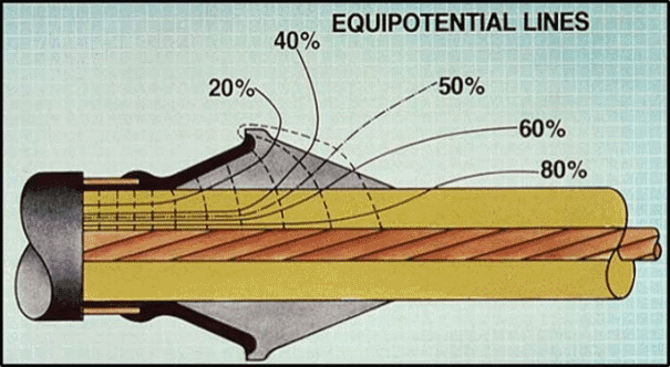
In this figure it can be seen that the earth shield of a cable (0%) is cut off, the equipotential lines (from 20% to 80%) concentrate at the edge of the earth electrode, causing high electrical stress.
Electric field enhancement at these points can produce local discharges that could lead to either flash over along the insulation surface or dielectric breakdown causing cable failure.
In cable installation, shielded power cables require electrical stress control when terminated.
Cable terminations and jointing are designed to eliminate the stress concentrationat the screen termination to avoid the break-down of the cable– electrical field has to be controlled in a cable termination and jointing.
The stress distribution at the conductor joint varies considerably due to changes in the profile introduced by the use of a ferrule.
Sharp edges and protrusions at the joint, if left unrelieved also result in abrupt change of the stress gradient.
It is therefore essential for the conductor to have a smooth profile so that there is no undue concentration of stresses.
However, the more important aspect of stress control applies to the location where the insulation screen is terminated.
It shall be noted that not only the dielectric stress increases in termination region, but also a potential gradient is set up along the interface between the dielectric and the surrounding medium.
The stress in the dielectric at the screen termination will be well above the design stress and may lead to premature failure.
In addition if the surrounding medium is air, or there is a void between the dielectric and the filling medium, then the stress in the area may cause the air to permit discharge even at the working voltage.
Paper is somewhat resistant to these discharges, but for polymeric insulation, like XLPE ( Cross-linked polyethylene ), such discharges will rapidly erode the dielectric and eventually result in failure.
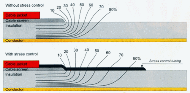
Without application of stress control, discharges would occur, adversely affecting the life of the joint and termination.
Figure 2 show the distribution of electric field without and with stress control.
Causes
Major weaknesses in the area of termination and joints of high and medium voltage cables requiring stress control are:
- Compression lugs allowing moisture to penetrate the conductor cores
- Failure to eliminate air pockets
- Core crossing resulting in partial discharge
- Poor cable preparation
- Moisture penetration
- Inadequate phase-to-phase and phase-to-earth clearance
- Tracking
- Poor jointing instructions
Related post Submarine Cables – Construction, Characteristics, Cables Laying & Joints
Methods of Stress Control
There is no universal termination or joint. There is a variety of different types of termination and joints each with advantages and disadvantages.
The optimization of cable terminations is achieved by investigating various constructions.
The proper termination method should provide good electrical and mechanical integrity.
To design a proper termination, an electric field distribution analysis should be done in the critical regions.
- Related post: Cable Size Calculation for LT & HT Motors
Stress Cone Method
The common method employed for stress control is the use of a stress cone that is shown in Figure 3.

The stress cone is a mean of controlling the capacitance in the area of screen termination, thereby reducing the dielectric stress along a gradient to tolerable limits at the point of termination.
The stress cone is extended beyond the screen termination, so that the potential gradient at the dielectric surface is reduced to a level where discharges will not occur.
In joints of high and medium voltage paper cables, the stress cone is usually built to a predetermined contour by hand application of insulating paper tapes, while in terminations the stress cone is either hand-applied or performed. With the development of polymeric and elastomeric cables, premoulded stress cones have also been introduced.
Before the stress cone is applied, it is necessary to reduce the electrical stress at the conductor joint, arising out of reasons explained earlier.
The concept is to provide a smooth profile so that the stress is evened out. This is obtained by ‘stepping’ of cable papers, which is achieved by removing the paper insulation in a set of steps, having risers and treads from the inner conductor surface to the outer insulation surface.
With the two cable ends so treated and joined together, hand applied impregnated paper tapes are applied over the assembly to form the joint dielectric.
- Related article: Wire & Cable Size Calculator in AWG
Heat Shrinkable Stress Control Tubing Method
Another common method is heat shrinkable stress control tubing that is used to control high electrical stresses at insulation screen terminating point in medium voltage plastic and paper insulated cable joints and terminations up to 36 kV.
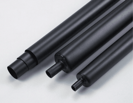
They also control the high stresses over the connectors in joints.
Stress control tubing is made from thermally stabilized cross linked high permittivity and high resistivity polymeric material.
Other Methods to Control Stress
Other methods are:
- High-resistance tapes or coatings, and materials with non-linear resistance layers, the material being of constant surface resistivity passes a small current and thereby sets up a linear voltage gradient along its length. A better stress distribution is achieved by using materials of non-linear resistivity, which also allows small current in the layer increase, the resistance of the material drop, and a smooth linear voltage gradient is achieved along the applied length.
- Materials having relative permittivity significance higher than the cable dielectric. The method is based on the principle that when materials of dissimilar permittivity are subject to a potential gradient across their combined thickness, the highest stress is experienced by the material having the lowest permittivity. It can be seen from the schematic diagram that the equipotential lines emerge gradually from the dielectric, thus producing a smooth gradient at the dielectric surface.
Related Articles:
- Why Power Transmission Cables & Lines are Loose on Electric Poles & Transmission Towers?
- What are Tiny Cylinder in Power Cords & Cable & Why?
- Why Coaxial Cables are Highly Insulated?
![]()


