Parallel Operation of DC Generators – Synchronization of Generators
Parallel Operation of DC Generators – Condition, Advantages and Load Sharing
In a power system network, power is supplied by many generators that are connected in an interconnected network. Instead of using a single large generator, many small DC or AC generators are operated in parallel.
Sometimes, the DC generators are used as the backup plant. In some conditions, it is not always possible to have a generator that fulfills load requirements. Hence, to meet the load demand, more than one unit of DC generators are connected in parallel.
Nowadays, the parallel operation of DC generators is used widely in the network to achieve the below advantages.

Advantages of Parallel Operation of DC Generators
The advantages of parallel operation are listed below.
Continuity of Supply
Continuity of supply is a prime requirement. If a power plant consists single unit of a generator, it is not possible to achieve this requirement. Because if a single unit of generator is in maintenance or at fault, the entire power plant stops to run load demand. Hence, if the power plant uses a greater number of generators instead of a single unit, the power plant can be used more reliably. Most of the customers (like a hospital, factories, etc.) needed an uninterruptable power supply.
Better Efficiency
In power plants, generators are designed to operate on full load. And it will get maximum efficiency at full load. But the power demand is not constant. It fluctuates between peak demand during the day and minimum demand during the night period. Hence, it is economical to use a small generator during the night period and a large generator during the day. If the demand increases, both generators are connected in parallel to meet the high demand efficiently.
Easy to Maintain and Repair
The generator requires periodical maintenance for long life and efficient operation. During maintenance, there must be another generator to run the load. Hence, it is easy to maintain generators. And also, if a breakdown occurs, it will take time to back in operation. In this condition, another generator can be used to meet the load demand.
Flexibility
The parallel connection of the generators offer greater flexibility compared to the single-unit large generator. A number of small generators can be connected together and it is located at different locations. The single large generator needed more space. Instead of that, a greater number of generators are installed at different locations.
Cost-Effective
The cost of electric power is reduced if the generators always operate at full load. When the load demand is high, a greater number of generators are connected in parallel. And when the load demand is low, a lesser number of generators are connected in parallel. Other generators remain on hold condition. Therefore, all generators are operating under full load conditions which reduces the cost of electrical power.
Easy to Make Additions
The electricity demand increases day by day. Hence, while constructing a power plant, always keep places for future expansion. Instead of building an entire power plant, it is easy to add more generators and connect them in a parallel manner to achieve more power demand.
Due to these advantages, parallel operation of the generator is widely used. As we know, the DC generators are classified into three types;
- DC shunt generator
- DC series generator
- DC compound generator
There is a difference in connection of armature and field winding in each type of generator. Hence, here we discuss how to connect each type of generator in parallel.
Parallel Operation of DC Shunt Generator
To connect two generators in parallel, their positive and negative terminals are must be connected with positive and negative terminals of the bus bar. The bus bar is a heavy copper bar and the terminals of the bus bar act as the terminals of an entire power plant.
The connection diagram of the parallel operation of the DC shunt generator is shown in the figure below.
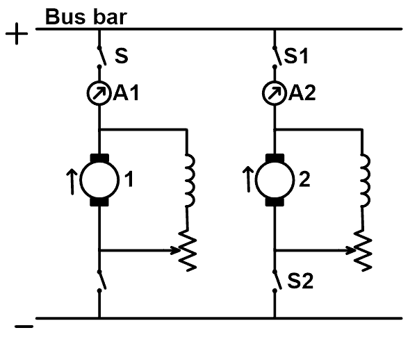
Here, the armature of generator 1 is connected across the bus bar. And it is used to supply the load. Now, we need to connect generator 2 with this system. For that, we need to connect generator 2 with the same polarity. Otherwise, a serious short circuit will occur that results in permanent damage in generators.
Before connecting generator 2, switch S is open. A voltmeter is connected across the switch. First, the armature of generator 2 is speeded up to the rated speed of the generator. The excitation of generator 2 is changed until the voltmeter shows zero reading. When it shows zero reading, it means that the terminal voltage is the same as the bus-bar voltage or generator 1 voltage.
Hence, after closing switch S, generator 2 is connected in parallel with generator 1. But generator 2 is not taking any load. Because the induced EMF of generator 2 is the same as bus bar voltage. So, there is no current to flow in the same potential difference. In this condition, generator 2 is known as a floating generator in the system.
The induced EMF of generator 2 must be higher than the bus bar voltage. In this condition, generator 2 delivers the load. The current supplied by generator 2 is;

Where,
- Ra = Resistance of armature circuit
- E = Induced EMF
- V = Bus bar voltage
The induced EMF of a new generator can be controlled by controlling the field. And by controlling induced EMF, we can control the share of the load.
Parallel Operation of DC Compound Generator
The connection diagram of two compound generators are connected in parallel is shown in the figure below.
The compound generator has rising characteristics. Hence, with the absence of any corrective devices, the parallel operation of DC compound generators is unstable. At the time of starting, each generator takes the same share of the load. Due to some reason, if the current passes through the series field winding of generator-1 increases, which further strengthens its field. This results in raises its generated EMF and it takes more load.
In this operation, we assumed that the load is constant. Hence, the share of the load of generator-2 is reduced and weakening its series field. This results in dropping off its load. This effect is cumulative After some time, the generator-1 takes the entire load. And generator-2 operates as a motor. In this condition, the circuit breaker of anyone generator will trip and stop this operation.
To make this operation stable, we need to use any corrective device with this system. In this parallel operation, the equalizer bar is connected to the armature end of the series windings. The equalizer bar is a conductor of low resistance. It is used to make the operation of over-compound and level-compound generators stable.
For example, generator-1 starts taking more share of the load. And its series field current increases. Now, this increased current passes through the series field winding of generator-1 and partly passes through the series field winding of generator-2. Hence both generators are affected in the same manner. In this way, generator-1 cannot take an entire load and generator-2 cannot be dropping off its entire load.
To maintain proper parallel operation and equal share of the load, the regulation of both generators must be the same and the series field resistance must be inversely proportional to the generator ratings.
Parallel Operation of DC Series Generator
The connection diagram of the parallel operation of two DC series generators is as shown in the figure below.
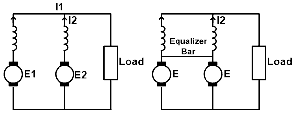
Here, we consider both generators are identical and take the same share of the load. But due to any reason, the induced EMF of generator-1 is increased (E1 > E2). In this condition, generator current I1 is greater than I2. This results in the strengthening of the series field of generator-1. And the weakening of the series field of generator-2.
This is a cumulative process. So, in the end, the entire load will be taken by generator-1 and generator-2 operates as a motor. Similar to the compound motor, this problem will be solved by using an equalizer bar. And due to this, two machines pass approximately equal currents to the load.
Load Sharing of DC Generator
The DC shunt generator has slightly dropping characteristics. Hence, it is the most suited generator for stable parallel operation. If one generator takes more or less load, due to its tendency to restore the original division of load, both generators immediately take proper load sharing.
In a condition of fault, one generator is out of service and its field is weakened. In this condition, the series field of another generator is increased. Thus, the breaker is open and the faulty generator removes from the system. This method of removing and connecting the generator makes the system reliable and it helps to prevent shock and sudden disturbance of prime mover as well as in the system.
The voltage characteristic of the shunt generator is as shown in the figure below.
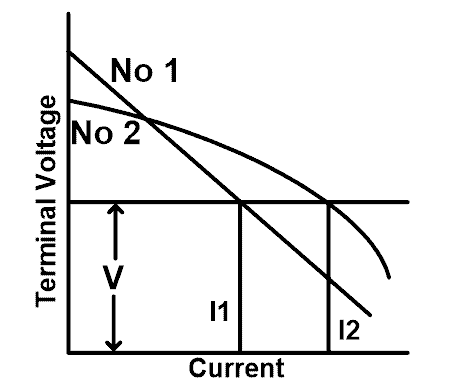
From the above characteristic, for the same terminal voltage V, generator-1 delivers I1 current and generator-2 delivers I2 current. The generator-1 has more drooping characteristic and deliver less current. Both generators will divide load equally at all points if their characteristics are similar and have the same voltage drop from no-load to full-load.
If two generators of different kVA ratings are connected in parallel, the load is shared according to their ratings. Their external characteristics plotted in terms of percentage full load current must be identical as shown in the figure below.

For example, one generator of 100 kVA and another generator of 200 kVA is connected in parallel with a 240 kW load. In this condition, the first generator will share 80 kW, and the second generator share 160 kW.
The combined characteristic of operation can be drawn if we know the individual characteristic of each generator. The current supplies by each generator can be found in the following figure.

The above results can be found by simple calculation instead of graphical representation if the generator has a straight line. Now, we calculate the load sharing portion which has unequal no-load voltage.
- E1, E2 = No-load voltage of two generators
- R2, R2 = Armature resistance
- V = common terminal voltage
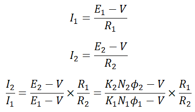
From the above equation, we can see that the bus bar voltage can be kept constant by increasing Φ2 or N2 or reducing N1 or Φ1. N2 and N1 are changed by changing the speed of driving engines and Φ1 and Φ2 can be controlled using shunt field resistances.
Related Posts:
- Difference Between Alternator and Generator with Comparison
- Synchronous Generator and Alternator Formulas & Equations
- Generator and Alternator Symbols
- Alternator / Generator MCQs with Explanatory Answers)
- EMF Equation of an Alternator and Synchronous Generator
- Why Generator & Alternator rated in kVA. Not in kW?
- DC Generator Formulas and Equations
- Generator Protection – Types of Faults & Protection Devices
- Difference Between AC and DC Generator
- Emergency Generator Set – Construction, Installation, Maintenance & Wiring
- How to Connect a Portable Generator to the Home Supply – 4 Methods


