EMF Equation of an Alternator and Synchronous Generator
EMF Equation of an Alternator and AC Generator
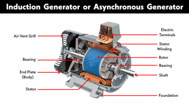
An alternator or synchronous generator (also known as AC generator or dynamo) is a device which converts mechanical energy into electrical energy. In today post, we will show the EMF equation of alternator and AC generators using two methods.
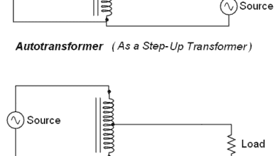
When we supply the magnetizing current by DC shunt generator through two slip rings (in recent alternators, they use electronic starting system instead of slip rings and commutators) because the field magnets are rotating. keep in mind that most alternators use a rotating magnetic field with a stationary armature.
When the rotor rotates, the stator conductors which are static in case of alternator cut by magnetic flux , they have induced EMF produced in them (according to Faraday’s law of electromagnetic induction which states that if a conductor or coil links with any changing flux, there must be an induced EMF in it.
Note: We will discuss the construction, working & operation, types of Alternators in details in our next posts.
This induced EMF can be found by the EMF equation of the alternator which as follow:
EMF Equation of Alternator
Lets,
P = No. of poles
Z = No. of conductors or Coil sides in series/phase i.e. Z = 2T…Where T is the number of coils or turns per phase (Note that one turn or coil has two ends or sides)
f = frequency of induced EMF in Hz
Φ = Flux per pole (Weber)
N = rotor speed (RPM)
Kd= Distribution factor = ![]()
Where Distribution factor = Kd =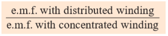
Kc or KP = Cos α/2
If induced EMF is assumed sinusoidal then,
Kf = Form factor = 1.11
In one revolution of the rotor i.e. in 60/N seconds, each conductor is cut by a flux of ΦP Webers.
dΦ = ΦP and also dΦ = 60/N seconds
then induced E.M.F per conductor ( average) = 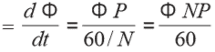 ….. (i)
But we know that:
f = PN / 120 or N= 120f / P
Putting the value of N in Equation (i), we get,
Average value of EMF per conductor = 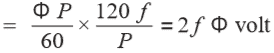 ∴ (N= 120f/P)
If there are Z conductors in series per phase,
then synchronous generator average E.M.F per phase = 2 f Φ Z Volts = 4 f ΦT Volts ….. (Z = 2T)
Also we know that;
Form Factor = RMS Value / Average Value
= RMS value = Form Factor x Average Value,
VAV = 1.11 x 4fΦT = 4.44fΦT Volts.
- (Note that is exactly the same equation as the EMF equation of the transformer)
And the actual available voltage of generator per phase
VPH = 4.44 KC KD f ΦTPH
V = 4.44 Kf KC KD f ΦT Volts.
Where:
- V = Actual generated Voltage per phase
- KC = Coil Span Factor or Pitch Factor
- KD = Distribution Factor
- Kf = Form Factor
- f = frequency
- T = Number of coils or number of turns per phase
Note: If alternator or AC generator is star connected as usually the case, then the Line Voltage is √3 times the phase voltage as derived from the above equation.
Alternatively, let show the EMF equation of AC generator as follow.
EMF Equation of Synchronous Generator
This equation is used to calculate the induced EMF in an alternator. Let’s derive the EMF equation for the alternator below.
Assume
P = No. Of poles
φ = flux per pole (Webers)
N = rotor speed (RPM)
As we know flux per pole is ‘φ’. Therefore each conductor is cut by a flux of ‘φP’. and The time taken by a pole to complete on revolution is ’60/N’ seconds.
So the average EMF per conductor becomes
Average EMF per conductor = φP/(60/N) = φNP/60
Where alternator speed, N is given by
f = PN/120 or N = 120f/P
Where ‘f’ is the frequency of induced EMF. Therefore the average EMF per conductor becomes
Average EMF per conductor = φNP/60 = (φP/60) x (120f/P)
Average EMF per conductor = 2fφ volts
Let Z = No. of conductors per phase, then the emf pretty phase becomes
EMF per phase = 2fφ x Z = 2fφZ
Let T = No. of turns (two conductors per turn), therefore Z = 2T and the equation becomes
EMF per phase = 2fφZ = 2fφ(2T) = 4fφT
Assume the induced EMF is sinusoidal, then its form factor
Form factor, kf = 1.11
Form factor = RMS value/ Average value
RMS value = form factor x Average value
RMS value per phase = 1.11 x 4fφT
Vrms per phase = 4.44 fφT volts
Now lets introduce ‘coil span factor kc‘ and ‘distribution factor kd‘ to get the actual induced EMF per phase.
Vrms per phase = Vph = 4.44 kckdfφT volts
Or
Vph = 2.22 kckdfφZ volts
This is the EMF equation of the alternator. Where
- Vph = Actual induced EMF per phase
- Kc = Coil span factor
- Kd = Distribution factor
- f = Frequency
- φ = Flux per pole (Weber)
- Z = No. of conductors
- T = No. of turns (Z=2T)
For star-connected alternator, the line voltage VL is √3 times the phase voltage
VL = √3 Vph
Related Posts:


Excellent Post About Emergency MELTDOWN Generators Shutdown and <a href="http://www.adpower.ae/" rel="nofollow">Ac generator parts</a>.<br />
Its very usefull……thanxxx
Nice but little lendi
Generator kV to hp Calculation explain …
what causes the breakdown of electricity