Generator Protection – Types of Faults & Protection Devices
Types of Generator Faults and Protection Devices
Common Generator Faults
Generator faults are usually classified into internal and external faults; internal faults are due to problems within the generator components and external faults are due to abnormal operating conditions and faults on external networks.
Faults on prime mover (Prime mover is the component that is used to drive the generator and may be combustion engines (the case of diesel generator sets), gas turbines, steam turbines, wind turbines and hydraulic turbines) and associated systems will not be discussed, since they are usually defined at mechanical design stage of the equipment.
However they must be integrated within generator protections for tripping purposes.
Types of Internal Faults in a Generator
Internal faults may be either electrical or mechanical
1. Stator Faults
- Windings overheating
- Windings phase-to-phase fault
- Windings phase-to-earth fault
- Inter-turn fault
2. Rotor Faults
- Earth fault
- Winding short-circuit (wound rotor)
- Overheating
3. Loss of Field / Excitation (The field in an AC generator consists of coils of conductors within the generator that receive a voltage from a source (called excitation) and produce a magnetic flux).
4. Generator Out-of-Step
5. Motor Operation
6. Bearings Overheating and lack of Pressure of Lubrication Oil
7. Vibration
Stator windings overheating may be caused by permanent overloads and phase-to-phase and earth faults are due to insulation breakdown.
Rotor winding short-circuit leads to an increase of excitation current and a decrease of excitation voltage.
Rotor overheating is a consequence of unbalanced currents at the stator, due to:
- Single-pole trip
- Stator winding fault
- Negative phase sequence
Negative phase sequence and unbalanced currents in the stator currents and produces an armature flux rotating in the opposite direction to the rotor, inducing eddy currents in the rotor mass.
These eddy currents, which are at twice the system frequency (50Hz or 60 Hz), will produce local overheating at the periphery of the rotor that may cause weakness in the rotor retaining wedges and rings.
When a generator loses excitation (or field), reactive power flows from the power system into the generator. The generator then loses synchronism and runs as an induction generator, above synchronous speed.
Above synchronous speed the rotor will start to oscillate in an attempt to lock into synchronism, resulting in overheating and other damage. As long as the system is stable, reactive power (MVAr) will flow into the generator and the machine will continue to put out active power (MW).
Generators motor operation may occur when the steam or water supply to the turbine fails and generators draws power from the electrical system.
In steam turbines the steam acts as a coolant, maintaining the blades at a constant temperature. Failure of the steam supply can cause overheating of the blades. On some machines the temperature rise is very low, and motoring can be tolerated for a considerable time.
Hydraulic turbine will have cavitation (formation and then immediate implosion of cavities in liquid – small liquid-free zones (“bubbles“) – that are the consequence of forces acting upon the liquid).
It usually occurs when a liquid is subjected to rapid changes of pressure that cause the formation of cavities where the pressure is relatively low.
Cavitation is a significant cause of wear. When entering high pressure areas, cavitation bubbles that implode on a metal surface cause cyclic stress through repeated implosion, resulting in surface fatigue of the metal.
Types of External Faults in a Generator
External Power System Faults and Abnormal Operating Conditions are:
- External short-circuit faults
- Non-synchronized connection of generator
- Out-of-step (pole slipping or loss of synch)
- Overloads
- Overspeed
- Phase unbalance and negative phase sequence
- Under and over frequency
- Under and over voltages
An uncleared or slow clearing fault on the network system can cause generators to start slipping poles, or go “out-of-step” with the rest of the system.
Such a condition is undesirable because harmful mechanical stresses are exerted on the shaft, and the severe power swings have a disturbing effect on the power system voltages.
Loose of synchronism may be caused by an external short-circuit, switching off of an important inductive load or by a fault at the excitation system.
Overspeed is the consequence of a suddenly switching off of the total load or an important reduction of load.
Generator Protection Devices
Generators are the most expensive pieces of equipment on power systems. The following devices are used for AC and DC generators protection against the faults occurs in it.
- Stator Earth Fault Protection (Stator windings phase-to-phase & stator ground or earth faults protection by Differential Relay)
- Rotor Earth Fault Protection
- Unbalanced Stator Loading Protection (Loss of field protection and change in reactive power flow)
- Protection against Stator Overheating (Stator windings and bearings overheating protection & Negative phase sequence protection)
- Protection against Loss of Boiler Firing
- Protection against Prime Mover & Turbine Failure (Stator phase unbalance protection)
- Overspeed & overexcitation Protection (core saturation due to overexcitation)
- Insulation Failure
- Protection against Lubrication Oil Failure
- Low Vacuum Protection
- Protection against Vibration & Under and over frequency protection
- Back up Protection of Generator
- Protection against Rotor Distortion & Phase supplementary start protection
- Protection against external short-circuit faults
- Protection against the difference expansion between stationary and rotating parts of generator
- Reverse Power Protection and Negative Power Flow Protection
Reliable protective relaying schemes are therefore required to detect and clear generator faults quickly to minimize damage and reduce repair time to a minimum.
Protection against stator windings phase-to-phase faults is performed through a differential relay, which principle was previously discussed at other sections. This protection device is not able to detect winding inter-turn faults.
When such a type of fault occurs phase voltage decreases and a zero-sequence voltage appears; this voltage is detected by a voltage relay (ANSI/IEEE/IEC code 60) connected to VT.
Stator ground or earth faults protection depends of stator grounding. For resistance grounding system an overcurrent relay connected to a “ring type” CT within the neutral connection or a voltage relay at resistance terminals may be used.
Under normal healthy conditions no current flows through the resistance and the voltage at the terminals is equal to zero.
For grounding through a transformer a voltage relay checking the voltage at the resistance connected to the secondary of the transformer is used.
Under normal healthy conditions the grounding transformer develops no secondary voltage, and no voltage is applied to the relay. When a stator ground fault occurs, a voltage is developed across the grounding transformer secondary terminals, and the voltage relay operates.
Figure 1 shows typical connection for stator differential and earth-fault protection.

Wound rotor winding short-circuit faults are protected by overcurrent relays.
The rotor windings may be damaged by earth faults.
The rotor or field winding on large thermal generators is ungrounded, thus a single ground fault produces no fault current.
A single ground fault, however, raises the potential of the whole field and exciter system, and the extra voltages induced by opening the field breaker, or the main generator breaker, particularly under fault conditions, may increase stress to the ground in the field, when the stator transients induce an extra voltage in the field windings. This extra voltage may cause a second fault on the field winding.
A second fault to ground may cause local heating of the iron which could distort the rotor, causing dangerous unbalance.
The protection against rotor earth-faults may be provided by a relay that controls the insulation of the rotor by applying an auxiliary AC voltage to the rotor or a voltage relay in series association with a high resistance (linear and non-linear resistors combination is the common method used nowadays) connected across the rotor circuit, the center point of which is connected to ground through the coil of a sensitive relay (ANSI/IEEE/IEC code 64).
Nowadays modern technique calls for the use combining linear and non-linear resistors.
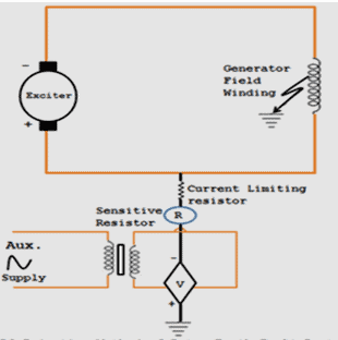
Figure 2 shows an example of rotor earth fault protection.
Loss of field protection uses a relay that detects the change in reactive power flow. A typical loss of excitation protection scheme uses an Offset Mho (impedance) relay to measure the generator load impedance.
The Offset Mho impedance relay is a single phase relay, and is supplied from the generator CT and VT. The loss of field relay will operate if the value of the load impedance falls within the operating characteristic of the relay.
A timing relay is included to initiate tripping of the machine if the leading reactive power condition persists for 1 s (typical).
To prevent core saturation due to overexcitation during run up and shutdown an overexcitation protection (ANSI/IEEE/IEC code 59) is used.
Overexcitation can be explained by the following equation:
B = V / f
Where B is the magnetic flux density or magnetic induction or core flux (unit: tesla – T), V is the applied voltage (unit: volt – V) and f the frequency (unit: hetz – Hz).
For the core flux to remain below the saturation point, the generator voltage may only be increased as the frequency (or speed) is increased.
If the excitation is increased too rapidly, then this overexcitation condition must be detected, and the field breaker tripped.
Overexcitation protection schemes use Volts per Hertz relays.
These relays have a linear characteristic, and will operate if the voltage divided by the frequency exceeds the set value.
Stator windings and bearings overheating protection is usually performed by RTD and thermistor to monitor the temperature.
Stator phase unbalance protection commonly uses a time-inverse overcurrent relay, which is set in accordance with the maximum time rotor can withstand this overheating.
The function of generator negative phase sequence protection is to protect the machine against the overheating effects, namely at the rotor, which occur as a result of unbalance of the stator phase currents.
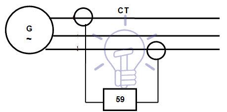
This protection uses a relay that compares the current at two phases through CT, as show in Figure 3.
Protections are set in accordance with the maximum time rotor can withstand this overheating and time is defined by the equation K = I2t (based in Joule law).
Typical curves for this condition is shown depend on the prime mover and are indicated by the manufacturer.
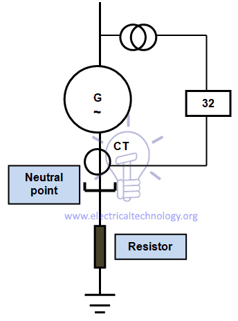
Reverse Power protection (ANSI/IEEE/IEC code 32) uses a power directional relay to monitor the generator load; the relay is supplied from the generator CT and VT as shown in Figure 4 and will operate when any negative power flow is detected.
Out-of-Step protection detects a condition caused by power system disturbances, rather than generator faults. The protection detects the condition when the generator slips its first pole, and causes the generator breakers to trip.
The turbine is not tripped enabling the machine to be re-synchronized after the system disturbance is cleared.
This protection can be considered complementary to Loss of Excitation protection.
The out-of-step condition occurs with the generator at full field and the loss of synchronism due to underexcitation occurs when the generator has no field.
Out-of-Step protection uses three impedance measuring relays. These relays are supplied by the generator CT and VT and measure the generator load impedance, detecting a power swing condition if the three relays operate in the correct sequence and will initiate tripping of HV circuit breakers.
For external short-circuit faults overcurrent relays are used (50; 50N; 51; 51N).
Under and over frequency protection (ANSI/IEEE/IEC code 81) detects also system disturbances, rather than generator faults. A major power system break-up can result in either an excess or insufficient generating power for the remaining connected load.
In the first case, overfrequency, with possible overvoltage results because of the reduced load demand. Operation in this mode will not produce overheating unless rated power and approximately 105% rated voltage are exceeded.
The generator controls should be promptly adjusted to match the generator output to the load demand.
With insufficient generation for the connected load, underfrequency is the result of heavy load demand.
The drop in voltage causes the voltage regulator to increase excitation. The result is that overheating can occur both in the rotor and the stator. At the same time, more power is being demanded, with the generator less able to supply it at the decaying frequency.
Automatic or manual transmission system load shedding should ideally adjust the load to match the connected generation before a total power system collapse occurs.
Over and under voltage relays (ANSI/IEEE/IEC codes 59 and 27) are used to control the voltage.
Phase supplementary start protection is provided to detect a condition where a fault exists when the generator is being run up to speed. Generators must not, of course, be started-up into a load or into a fault condition.
To prevent this, a scheme of protection is used that switches into service low-set overcurrent relays ONLY if the frequency is below 52 Hz on 60 Hz power systems and 42 Hz on 50 Hz systems.
Nowadays IED (see Section 2.1) that group all required protection functions are commonly used for generator protection.
![]()
Related Posts:
- Motor Protection – Types of Faults and Protection Devices
- Cables Feeder Protection – Faults Types, Causes & Differential Protection
- Overhead Lines Faults & Protection
- Power Transformer Protection & Faults
- Power Transformers Maintenance, Diagnostic & Monitoring
- Transformers Fire Protection System – Causes, Types & Requirements
- How To Locate Faults In Cables? Cable Faults, Types & Causes
- Fault Current Limiter and Their Types
- GFCI: Ground Fault Circuit Interrupter. Types, Working & Applications
- All About Electrical Protection Systems, Devices And Units


