Torque-Slip and Torque-Speed Characteristics of Induction Motor
Torque-speed & Torque-slip Characteristics of an Induction Motor
Torque-slip Characteristics
Torque-slip characteristics give the relation between torque and slip. The torque-slip characteristics show how the torque changes with a change in slip. The slip is defined as a ratio of synchronous speed and the actual speed of the rotor. The actual speed of the rotor varies with loading condition. Therefore, the slip changes with loading condition.
In the previous article, we have derived the torque equation of an induction motor.

From the above equation, if R2 and X20 are kept constant, the torque depends on the slip. The torque-slip characteristics curve looks like a rectangular hyperbola. And this curve is divided into three regions;
- Low slip region
- Medium slip region
- High slip region
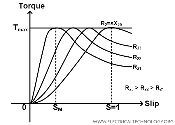
The curve for torque-slip characteristics for different values of rotor resistance is shown in the figure below.
Related Post:
Low Slip Region
At synchronous speed, the slip of an induction motor is zero. Hence, the torque developed in the rotor is zero. Therefore, an induction motor always runs slightly less than the synchronous speed. And in this condition slip is very low.
When the slip is very low, (sX20)2 is negligible compared to the R2. So, for low slip conditions,

If we consider rotor resistance R2 as constant;
T ∝ s
Hence, at low slip conditions, the torque is directly proportional to the slip. This is the normal operating region for an induction motor. In the low-slip region, the torque-slip curve is a straight line.
Medium Slip Region
If the load increases, the speed of an induction motor decreases, and slip increases. As the slip increases, the term (sX20)2 becomes high compared to Rotor resistance R2. And in this condition, we can neglect the rotor resistance R2.
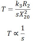
So, the torque is inversely proportional to the slip. During this region, the curve shapes a rectangular hyperbola and passes through the point of maximum torque. The maximum torque is achieved when R2 = sX20. This torque is known as pull-out torque or breakdown torque.
High Slip Region
If we increase the torque beyond the maximum torque point, the torque starts decreasing. This condition is when the load increases. During this condition, the motor speed decreases, and the overload protection must be activated to disconnect a motor from the supply. If the motor continuously runs in this region, the motor will damage due to overheating. This region in a torque-slip curve is decreasing region after the maximum torque point.
Generally, the induction motor operates for the value of slip between zero to SM. The slip SM is a slip at the maximum torque point. The pull-out torque for an induction motor is 2 to 3 times of rated full-load torque for typical operation. Therefore, the motor can handle overload for short period without stalling.
The torque-slip curve of the induction motor for constant rotor resistance is shown in the figure below.
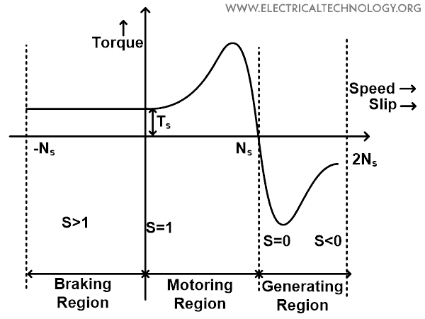
Similar to the above description, this curve is also divided into three parts;
- Motoring region
- Generating region
- Breaking region
Motoring Region
In this mode of operation, the slip of an induction motor is between zero to one. When the stator is supplied by electric power, the rotor rotates below synchronous speed. And the torque of a motor varies from zero to full-load torque as slip varies from zero to one.
During this condition, the torque is directly proportional to the slip. Generally, the induction motor operates in this region. The slip is zero at synchronous speed and the slip is one at standstill condition.
Generating Region
In generating mode of operation, the induction motor runs above the synchronous speed and it behaves as an induction generator. The speed of a motor increases above synchronous speed with the help of external devices like a prime mover.
During generating region, the slip and torque both are negative. Hence, the machines receive mechanical energy and deliver electrical energy. During the generating region, the motor requires to supply reactive electric power.
Braking Region
In the braking region, the polarity of supply voltage is changed. Hence, the motor rotates in a reverse direction. This mode is used to stop the motor. This method of electrical braking is known as plugging. During braking mode, the slip is greater than one.
By this method, the motor stops within a short time. But the kinetic energy stored in the load is dissipated as heat. Therefore, during the breaking, a very high amount of heat is generated. And also, if the stator is connected with the supply, it is also generated as heat. Hence, it is contained to disconnect the supply from the stator before entering the braking mode.
- Related Post: Power, Voltage and EMF Equation of a DC Motor

Torque-Speed Characteristics of Induction Motor
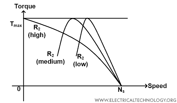
The torque-speed characteristic is a curve between the torque and speed of an induction motor and it is shown in the figure below.
The below equation gives the speed of the rotor at which the maximum torque is achieved.
NM = NS (1-SM)
The equation of maximum torque is;

Here, we can see that the maximum torque is independent of rotor resistance. But the exact location of maximum torque is dependent on rotor resistance. Greater the value of rotor resistance, the greater the value of slip at which the maximum torque is achieved.
From the torque-speed curve, it is clear that as the rotor resistance is increases, the pull-out speed of the motor decreases (the maximum torque remains constant).
Related Posts:
- Types of Electric Motors – Classification of AC, DC & Special Motors
- Applications of Electric Motors
- Single-Phase Induction Motor – Construction, Working, Types & Applications
- Three-Phase Induction Motor – Construction, Working, Types & Applications
- Motor Starter – Types of Motor Starters and Motor Starting Methods
- Direct Online Starter – DOL Starter Wiring Diagram for Motors
- Cable Size Calculation for LT & HT Motors
- Speed Control Methods of of a DC Motor
- DC Machine – Construction, Working, Types and Applications
- Servo Motor – Types, Construction, Working, Controlling & Applications
- Brushless DC Motor (BLDC) – Construction, Working Principle & Applications
- Stepper Motor – Types, Construction, Operation & Applications
- What is Motor Efficiency and How to improve it?
- Induction Motor & Linear Induction Motors Formulas & Equations
- What is Motor Generator Set and How Does it Work?
- How to Run a Three-Phase Induction Motor on a Single-Phase Power Supply?
- Electrical & Electronics Engineering Formulas & Equations
- Electric Motors Symbols


Helpful
Very nice.
Thank you