Equivalent Circuit of Induction Motor
What is the Equivalent Circuit of Induction Motor?
An induction motor works on the principle of electromagnetic induction. The working of an induction motor is similar to the transformer. Also, an equivalent circuit of an induction motor is similar to the equivalent circuit of a transformer. The energy transfers in an induction motor from stator to rotor is a quite similar operation as energy transfers in the transformer from primary to secondary.
The induction motor is an asynchronous motor. And the speed of a motor depends on the loading condition. With the help of an equivalent circuit, we can evaluate the steady-state operation of the motor by simple network calculation and it enables us to find the performance characteristics like rotor torque, losses, and efficiency of the motor.
The induction motor always run below synchronous speed. The relative speed between the synchronous speed and actual rotor speed is known as slip. The equation of slip and synchronous speed is shown in the below equation.
 Where,
- Ns = Synchronous speed
- N = Speed of rotor (actual speed)

Where,
- f = Supply frequency
- p = Number of poles
Related Posts:
- Equivalent Circuit of Electrical Transformer
- Power, Voltage and EMF Equation of a DC Motor – Formulas
The equivalent circuit of an induction motor is drawn only for one phase.
Stator Circuit Model
The stator model of an induction motor is shown in the figure below.
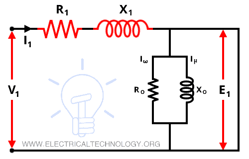
The stator consists of the stator winding and stator core. The loss produced in the stator winding is represented by the stator resistance R1 and the loss produced in the stator core is represented by the stator reactance X1. Therefore, the stator circuit model consists of a stator resistance and stator reactance connected in series.
The no-load current I0 is divided into two parts; magnetizing current Iμ and core-loss current Iω.
I0 = Iμ + Iω
A pure inductive reactance X0 carries magnetizing current Iμ and non-inductive resistance carries core-loss current Iω.
Due to the higher reluctance caused by the air gap in the case of the induction motor, the total magnetizing current is larger compared to the transformer. In an induction motor, the no-load current is 25 to 40% of the rated current and in a transformer, the no-load current is 2 to 5% of the rated current. The no-load current varies for different sizes and types of motors.
Related Posts:
- Single-Phase Induction Motor – Construction, Working, Types & Applications
- Three-Phase Induction Motor – Construction, Working, Types & Applications
Rotor Circuit Model
When a three-phase supply is given to the stator winding, the EMF is induced in the rotor winding. The rotor voltage depends on the relative motion of the rotor and stator magnetic field. The largest relative motion is achieved at standstill condition. The rotor voltage induced at any slip is given by;
E2s = sE20
If we ignore the skin effect, the rotor resistance is constant and it is independent of the slip. The rotor reactance depends on the rotor frequency and inductance. The rotor reactance is given by;
X2 = 2πf2 L2
Where;
- f2 = rotor frequency
- L2 = rotor inductance
The relation between supply frequency f1 and rotor frequency f2 is given by;
f2 = sf1
X2 = 2 πsf1 L2
X2 = sX20
Where;
X20 = standstill reactance of rotor
The circuit diagram of the rotor circuit model is shown in the figure below.
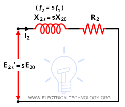
From the above figure, the rotor impedance is given by;
Z2s = R2 + jX2s
Z2s = R2 + jsX20
The rotor current is given by;

Related Post:
This equation represents by the above figure-2. From this equation, it is noted that I2s is a slip-frequency current produced by slip-frequency voltage sE20 and rotor circuit having an impedance of R2 + jX2s.
If we divide the above equation by slip s, we get;

The representation of this equation is shown in the figure below.
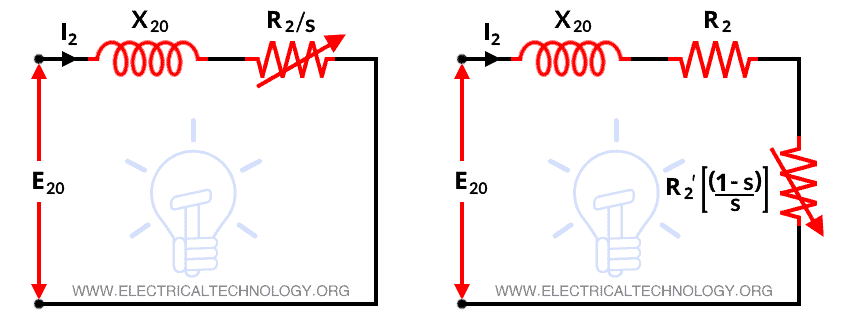
Here, we can see that the magnitude and phase angle of I2s remains unchanged by this modification. Then also there is a huge difference between both equations. In equation-2, I2s is produced by constant line frequency voltage E20 and the rotor circuit has an impedance of (R2/s) + jX20. Therefore, I2s in equation-2 is a line frequency current and I2s in equation-1 is a slip-frequency current.
Also, in fig-2, the rotor circuit model has a constant resistance R2 and variable leakage reactance sX20. And in fig-3, the rotor circuit model has a constant leakage reactance X20 and variable resistance R2/s.
This equation describes similarity with the secondary winding of transformer having a constant voltage ratio and same frequency of both sides. Here, we assume a stationary rotor that carries the same current as the actual rotating rotor and produces the same MMF. This imaginary stationary rotor makes it possible to transfer secondary (rotor) impedance to the primary (stator) side.
In the case of induction motor, when the rotor current and voltages are referred to stator side, their frequency is also changed to stator frequency.
Related Posts:
- Difference Between Single Phase & Three Phase Induction Motor
- What is the Role of Capacitor in a Ceiling Fan Motors?
Exact Equivalent Circuit of Induction Motor
To derive the exact per-phase equivalent circuit of an induction motor, we need to calculate the rotor part of a model over to the stator circuit’s frequency and voltage level. In the transformer equivalent circuit, the voltage, current, and impedance on the secondary side are transferred to the primary side with the help of the turns ratio (a).
A similar transformation can be done in the case of the induction motor.
E2‘ = a E2 = E1

R2‘ = a2R2
X20‘ = a2X20
The exact equivalent circuit of the induction motor is shown in the figure below.
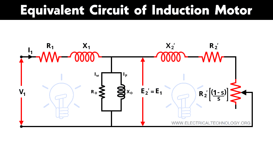
This equivalent circuit is identical to the two-winding transformer.
Related Posts:
Approximate Equivalent Circuit of Motor
Like a transformer, in this case, also we can derive an approximate equivalent circuit by shifting the shunt impedance branches R0 and X0 to the input terminals. In an approximate equivalent circuit, we need to assume that;
V1 ≈ E1 = E2‘
The approximate equivalent circuit of the induction motor is shown in the figure below.
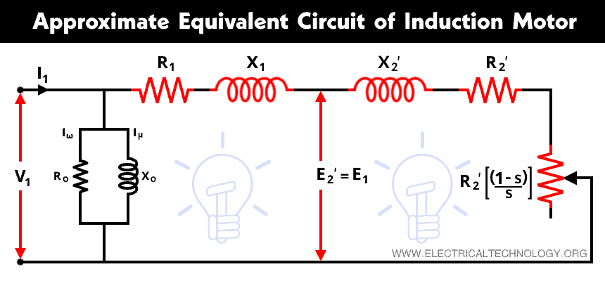
As shown in the above figure, one resistance depends on the slip s. This resister represents the developed mechanical power by the rotor. All other components are constant. Reactances shown in the figure correspond to the fixed stator frequency f1.
Related Posts:
- Difference between Synchronous and Asynchronous Motor
- Why We Need to Install a Starter with a Motor?
- What is Motor Starter? Types of Motor Starters and Motor Starting Methods
- Difference Between AC and DC Motors
- DC Machine – Construction, Working, Types and Applications
- Star Delta Starter – (Y-Δ) Starter Power, Control and Wiring Diagram
- STAR-DELTA Starter Motor Starting Method Without Timer
- Speed Control of DC Motor – Voltage, Rheostatic & Flux Control Methods
- Brushless or BLDC Motor – Construction, Working & Applications
- Difference Between Brushed and Brushless Motor
- Servo motor – Construction, Working & Applications
- Induction Motor & Linear Induction Motors Formulas & Equations
- Why Motor rated in kW instead of kVA?
- Direct Online Starter – DOL Starter Wiring Diagram for Motors
- Cable Size Calculation for LT & HT Motors
- What is Motor Efficiency and How to improve it?
- Motor Protection – Types of Faults and Protection Devices
- How to Run a Three-Phase Induction Motor on a Single-Phase Power Supply?
- What happens if You Connect a 3-Φ Induction Motor to 1-Phase Supply?
- What happens to the 3-Phase Motor When 2 Out of 3 Phases are Lost?
- What happens to the 3-Phase Motor When 1 Out of 3 Phases is Lost?
- Applications of Electric Motors